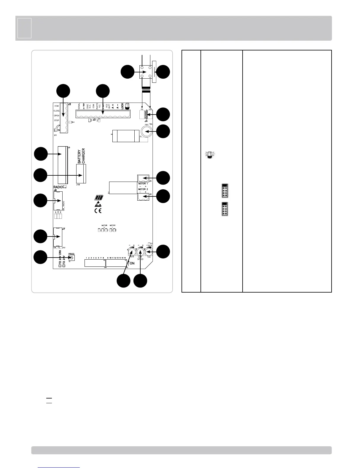
G
B
B - SETTINGS
DIP 1 (ON) - MOTOR ROTATION DIRECTION CONTROL (POINT C)
DIP 2 (ON) - TIMER (POINT D)
DIP 3 (ON) - ACTIVATES DOOR RELEASE DURING PHASES OF SLOWDOWN AND TOTAL OPENING
AND CLOSING (AS PER THE IMPACT TESTS OF EN12453)
DIP 1-2 MEMORIZATION/CANCELLATION OF RADIO CONTROL CODES FOR TOTAL OPENING (ONLY
MODEL CRX) (POINT E)
DIP 1-3 MEMORIZATION/CANCELLATION OF RADIO CONTROL CODES FOR PEDESTRIAN OPENING
(ONLY MODEL CRX) (POINT F)
DIP 2-1 MICRO-SWITCH CONTROLLER FOR PEDESTRIAN OPENING TIMER
DIP 4 Photocells always active (OFF) - Photocells active only during closing (ON)
DIP 5 Pre-blinking (ON) - Normal blinking (OFF)
DIP 6 Single pulse command (K BUTT) and step-by-step radio receiver (OFF) - automatic (ON)
DIP 7 Power sensor operation (ON-activated) time operation (OFF-activated).
DIP 8 Electric lock activation (ON-activated)
DIP 9 Electric lock pulse release (ON-activated)
DIP 10 Electric lock pulse engagement (ON-activated)
DIP 11 Easy release activation (ON-activated)
DIP 12 Sensor TEST activation (ON-activated).
DIP 13 Selection of 1 or 2 motor operation (default OFF 2 motors)
DIP 14 OFF
DIP 15 OFF
DIP 16 IMMEDIATE CLOSING AFTER PASSING IN FRONT OF PHOTOCELLS
ON ACTIVATED
OFF DEACTIVATED
JP1 => Check that the jumper is inserted!
JP2 => Check that the jumper is inserted!
JP3 => Check that the jumper is inserted!
PROG => S3 Programming button
ADJUSTMENTS
ATTENTION: PUT DIP 3 IN THE ON MODE ONLY AFTER HAVING CARRIED OUT ALL THE PROGRAMMING
PROCEDURES.
NOTE: WITH DIP 3 (ON) BRIEF GATE REVERSAL AFTER IMPACT IS ACTIVATED.
THIS BRIEF GATE REVERSAL PERMITS STATIC FORCE TO BE REDUCED TO ZERO WITHIN 5 SECONDS AS
PER STANDARD EN12453 POINT A.2.2 (ACCEPTABLE STATIC FORCE), THEREBY COMPLYING WITH THE
IMPACT TESTS ALSO OUTLINED BY EN12453).
IF COMPLIANCE WITH THE AFOREMENTIONED STANDARD IS UNNECESSARY, SIMPLY POSITION DIP 3 TO
OFF. IN THIS CASE THE GATES STOP WITHOUT REVERSING.
RUN TRIMMER (TR1) high-speed electronic regulator
This trimmer permits motor speed adjustment (the default setting is maximum speed). Adjustment of the automation
is useful for compliance with European impact standards.
LOW-SPEED TRIMMER (TR2) Electronic slow speed approach control
The slow speed control is performed by adjusting the LOW- SPEED TRIMMER which changes the voltage output
across the motor(s) (turning it clockwise increases the speed). Adjustment is performed to determine the correct
speed at the end of opening and closing according to the gate or when there is friction that might cause the system
to function poorly.
AUTOMATIC CLOSING TRIMMER - TCA (TR3) TOTAL OR PEDESTRIAN default NOT ACTIVATED and LED
DL6 OFF (TRIMMER FULLY ROTATED COUNTERCLOCKWISE)
This trimmer makes it possible to adjust the time for total or pedestrian automatic closing. Only with gate completely
(total) or partially (pedestrian) open and LED DL6 on (trimmer rotated clockwise).
The pause time can be adjusted from a minimum of two seconds up to a maximum of two minutes.
LED SIGNALS
DL1 program activated (red)
DL2 gate opening M2 (green)
DL3 gate closing M2 (red)
Power supply 230 Vac 50/60 Hz - external to the control
panel - (120V/60Hz upon request)
Common contact
Closing impulse contact (NA)
Opening impulse contact (NA)
STOP impulse contact (NC)
Radio Antenna
Gate open state and battery state output indicator (24Vdc
3W max)
+ 24Vdc safety strip self-test power supply
Safety strip contact (NC)
Common contact
Photocells contact (NC)
Single pulse contact (NO)
Pedestrian opening contact (NA)
+ 24Vdc accessories power supply
- 24Vdc accessories power supply
Electric lock connection (MAX 15W 12V)
- 24Vdc blinker (code ACG7061) power supply. Pay
attention to the polarity.
Connection to secondary coil of transformer 18 Vac
MOTOR 1 CONNECTION (without polarity)
MOTOR 2 CONNECTION (without polarity)
Connector dedicated to the factory programming.
DO NOT REMOVE ANY JUMPER!
OTHERWISE THE OPERATOR WILL NOT WORK!
Connector dedicated to the factory programming (only CRX
control board)
DO NOT REMOVE ANY JUMPER!
OTHERWISE THE OPERATOR WILL NOT WORK!
Built-in radio module (model CRX), or connector for radio
receiver RIB, 24 Vdc supply
Connector for charge card of 24Vdc battery (code
ACG4648)
Trimmer for high speed adjustment operations
Trimmer for low speed adjustment operations
Trimmer for automatic closing time adjustment (DISABLED
DEFAULT AND DL6 LED OFF)
Programming button
Motor protection fuse
Transformer protection fuse
TRANSFORMER
J1
J2
J3
J4
J5
J6
J7
J8
J9
J10
TR1
TR2
TR3
S3
FUSE 1
F1
N F
COM.
CLOSE
OPEN
STOP
AERIAL
SIGNAL
A+TEST
EDGE N.C.
COM.
PHOTO N.C.
K BUTT.
PED. BUTT.
A+
A -
LOCK
SECONDARY
TRANSFORMER
MOTOR 1
MOTOR 2
SW T2 24V
SW RADIO
RADIO
BATTERY
CHARGER
TRIMMER RUN
TRIMMER LOW SPEED
TRIMMER TCA
PROG
T 8 A
T 2 A
J3
TR2TR1
J2
J4
F1
FUSE 1
J5
J6
TR3
J10
J8
J9
J1
J7
S3
A - CONTROL PANEL FEATURES
 Loading...