● The electronic load was turned on before the RD6018 output was turned ON.
● Graphing was started about 15 seconds before the RD6018 output was turned ON.
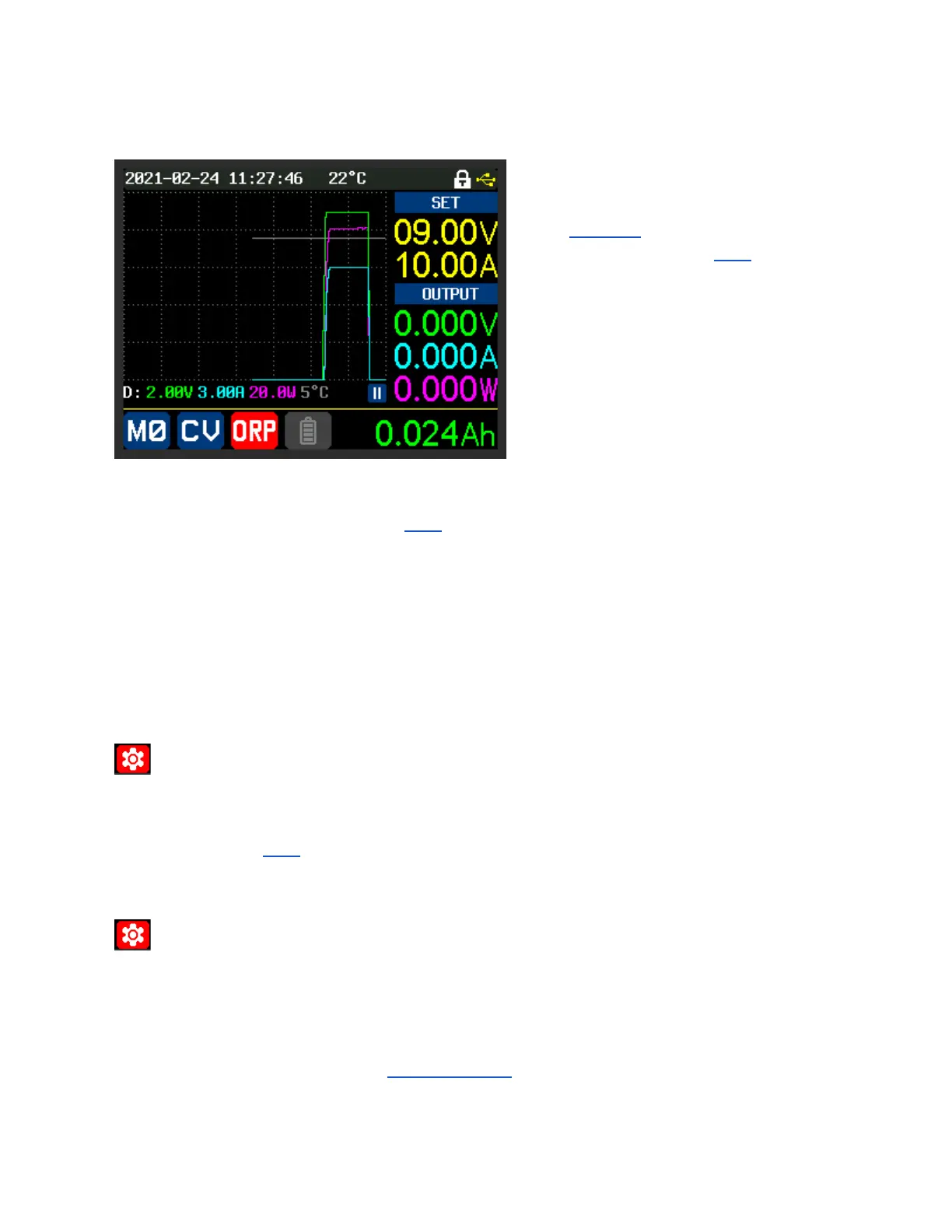
This graph shows:
● RD6018 output was 9 Volts and 9 Amps, in
CV mode, for approximately 10 seconds.
● After that time, the ORP tripped out.
This shows the ‘ORP delay’ setting waits
approximately 10 seconds (the set value) before
determining whether ‘ORP’ should trip.
(In this example it does trip because the effective
load resistance is 1 Ω, which is less than the ORP
set value of 1.12 Ω.)
Measured on an oscilloscope (not shown), with the ‘ORP delay’ at its minimum value of 0.1 seconds,
and the 5 Ω resistor setup used in the ‘ORP’ example:
ORP tripped at 0.14 seconds from the ON button being pressed.
(Measured from when the output voltage started to rise above zero.)
With the RD6018 already ON, it took about 0.7 seconds to trip after the 5 Ω resistor was
connected.
ORP set
➥Power Settings or Quick Setting Menu (“SHIFT” + “▼”)
Value Set in 0.01Ω steps, starting from 0.01Ω
See ‘ORP’ Setting for details on use.
OTP (ext) (Over Temperature Protection - External Sensor)
➥Power Settings
OFF Unit does not monitor for Over Temperature events on the external probe.
Value Set in 1°steps
IF Set AND the temperature reaches, or exceeds, the set value:
● Unit will enter Protection Mode.
● The output will immediately turn OFF.
● The “ON/OFF” Button will turn off its illumination,