EasyManua.ls Logo

RIDGID 700 - User Manual

RIDGID 700
43 pages
Print Icon
To Next Page IconTo Next Page
Loading...
• Français – 13
• Castellano – pág. 27
Portable Power
Drive
OPERATOR’S
MANUAL
700
WARNING!
Read this Operator’s Manual
carefully before using this tool.
Failure to understand and fol-
low the contents of this manual
may result in electrical shock,
fire and/or serious personal
injury

Table of Contents

Other manuals for RIDGID 700

Questions and Answers

  • J
    Jeffrey LoweJul 26, 2025
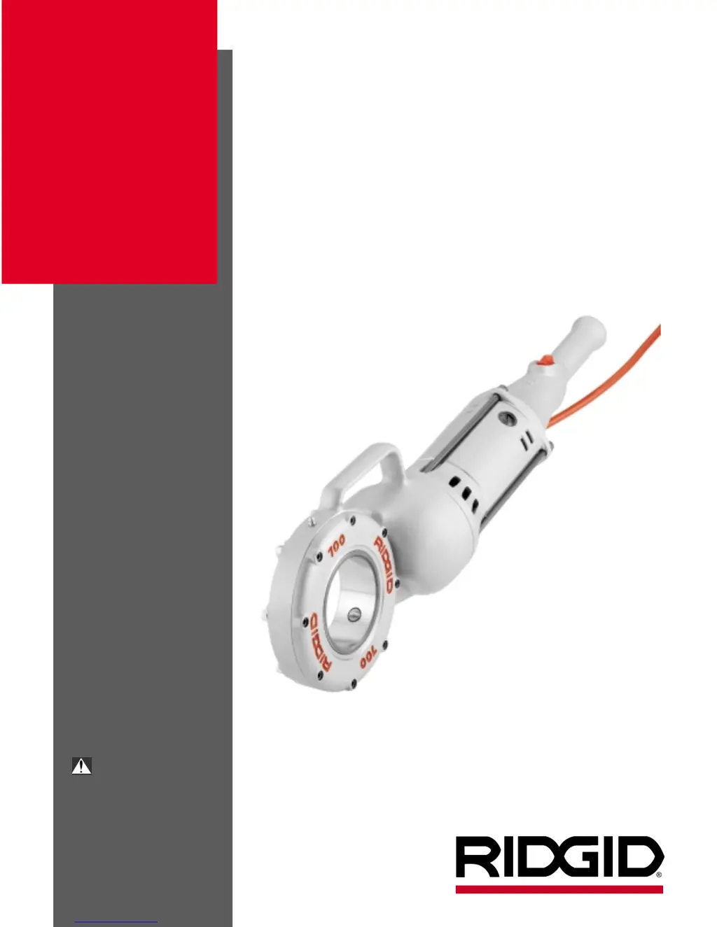
    How to troubleshoot a RIDGID 700 Power Tool that won't start?
    • Q
      qcooperJul 26, 2025
      If the RIDGID Power Tool motor doesn't start, first ensure it's plugged into a power source. If it is, check the fuse and replace it if blown. Also, inspect the brushes to ensure they are making contact with the armature; replace them if they're worn.
  • H
    hawkinsjoannaJul 30, 2025
    Why does my RIDGID 700 motor sound overloaded?
    • A
      alexanderdixonJul 31, 2025
      If the RIDGID Power Tool motor sounds overloaded, it might be due to dull dies. Replace the dies. Ensure you are using RIDGID thread cutting oil in adequate quantity. Also, check the screws to make sure brush is pressed firmly onto commutator. Replace worn brushes and use only original brushes. If there is a sharp edge on brush, break the edge.
  • R
    Ryan BaileyAug 5, 2025
    What to do if my RIDGID 700 Power Tool produces damaged threads?
    • A
      Ashley MurphyAug 5, 2025
      If the RIDGID Power Tool produces a damaged thread, the dies may be dull or broken, so replace them. Ensure the machine is running in the correct direction by checking the direction switch setting. Reset improperly set dies and ensure they are assembled in the correct sequence. Use only good quality pipe and adequate quantity of RIDGID thread cutting oil.
  • S
    Sean GentryAug 9, 2025
    Why is the support arm on my RIDGID 700 Power Tool turning while threading?
    • J
      Joshua LivingstonAug 10, 2025
      If the support arm of your RIDGID Power Tool turns while threading, ensure the support arm feedscrew is tight. Clean the support arm jaws with a wire brush and make sure the support arm sits square on the pipe.
  • H
    Holly LevineAug 14, 2025
    What causes die heads on my RIDGID 700 to not change properly?
    • K
      Katelyn VaughanAug 14, 2025
      If the die heads of your RIDGID Power Tool cannot be changed properly, eliminate any burr with a file that has occurred at the spline end of the die head.
  • C
    Christopher KingAug 19, 2025
    Why are sparks forming at the motor of my RIDGID 700 Power Tool?
    • J
      Joshua LivingstonAug 19, 2025
      If sparks are forming at the motor of your RIDGID Power Tool, check that the brushes are making proper contact with the commutator. If there is bad contact between brushes and brush holder, tighten the screws, make sure brush is pressed firmly onto commutator. Replace worn brushes. Only use original brushes.

Summary

General Safety Information

Work Area Safety

Keep work area clean, avoid explosive atmospheres, keep bystanders away, keep floors dry.

Electrical Safety

Use grounded outlets, avoid body contact with grounded surfaces, keep connections dry, use proper extension cords.

Personal Safety

Stay alert, dress properly, avoid accidental starting, remove wrenches, don't overreach, use safety equipment.

Tool Use and Care

Tool Use Guidelines

Secure workpiece, don't force tool, check switch, disconnect power before adjustments, store safely, maintain tools.

Tool Maintenance and Care

Keep cutting edges sharp, check for misalignment, use recommended accessories, keep handles dry.

Specific Safety Information

Power Drive Safety Precautions

Follow instructions for threading, use support arm for large pipe, do not use if switch is broken, avoid loose clothing.

Description, Specifications and Standard Equipment

Product Description

Provides rotational motion for threading pipe, conduit, rod, with forward/reverse switch.

Technical Specifications

Details threading capacity, motor type, HP, volts, amps, switch, speed, gear head, body, length, weight.

Available Accessories

Lists adapters, oiler, support arm, carrying case, and vises for the Power Drive.

Power Drive Inspection

Daily Inspection Checklist

Check plug, cord, brushes, parts for damage, binding, or misalignment. Lubricate if needed.

Tool and Work Area Set-Up

Work Area Requirements

Ensure adequate lighting, no flammables, grounded outlet, clear path, dry place, level ground.

Tool Setup Procedures

Plug into outlet, check power cord, ensure tool operates properly by testing switch.

Operating Instructions For Threading With Drop Head Die Heads

Setup for Drop Head Threading

Install die head, secure pipe in vise, fill oiler, position support arm, use pipe wrench if needed.

Drop Head Threading Procedure

Place die head, start thread, apply oil, keep switch depressed, release when done, back off die head.

Operation Instructions For Threading With Geared Threaders

Geared Threader Setup and Handling

Proper setup is required to prevent tipping. Geared threaders are heavy, requiring two people to lift.

Adjusting Geared Threaders

Covers cam plate (pipe size) adjustment and thread size adjustment procedures.

Changing Posts For Straight Or Tapered Threads

Guide Post Adjustment

Guides for setting straight or tapered threads by adjusting guide post and angle slots.

Changing Die Set

Die Set Replacement Steps

Steps to remove stop screw, rotate cam plate, remove old dies, and insert new dies.

Threading With Geared Threaders

Geared Threading Procedure

Position pipe, install adapter, adjust threader, tighten workholder, apply oil, engage drive, thread pipe, back off.

Troubleshooting Guide

Motor Troubleshooting

Covers motor not starting or sounding overloaded, including causes and corrections.

Threading and Die Head Issues

Addresses die head problems, damaged threads, and support arm issues.

Accessories Listing

Power Drive Specific Accessories

Lists adapters, support arm, carrying case, oiler, and grease for the Power Drive.

Compatible Threaders

Lists drop head and geared threaders compatible with the Power Drive.

Maintenance Instructions

Motor Brush Maintenance

Instructions for checking and replacing motor brushes.

Lubrication Schedule

Guidance on greasing face gear and bearings periodically.

Proper Tool Storage

Advises storing the power drive indoors or covered, in a locked area away from children.

Service and Repair

Authorized Service Procedures

Emphasizes using qualified personnel and identical replacement parts for service.

Wiring Diagrams and Schematics

Wiring Color Codes

Shows wiring colors for 115/230V systems and installation of brush lead wires.

230 V Wiring Schematic

Provides a schematic for 230V wiring with a line filter, including European color codes.

RIDGID Lifetime Warranty

Warranty Coverage Details

States the warranty covers defects in workmanship and material for the lifetime of the tool.

How to Obtain Service

Explains how to obtain service and what the company will do to correct problems.

Warranty Exclusions and Limitations

Details what is not covered, including misuse, abuse, and consequential damages.

RIDGID 700 Specifications

General IconGeneral
TypePipe Threader
MotorUniversal
Power1/2 HP
Motor TypeUniversal
Pipe Capacity1/8 inch to 2 inches
Weight25 lbs
Bolt Capacity1/4 inch to 1 inch
Voltage115V

Related product manuals