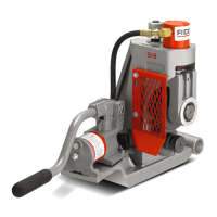
918 Roll Groover
Ridge Tool Company10
lengths listed in
Chart A
must be supported with 2
pipe stands. The second pipe support should be lo-
cated
3
/
4
of pipe length from roll groover.
Failure to use two stands may result in the
unit tipping or the pipe falling.
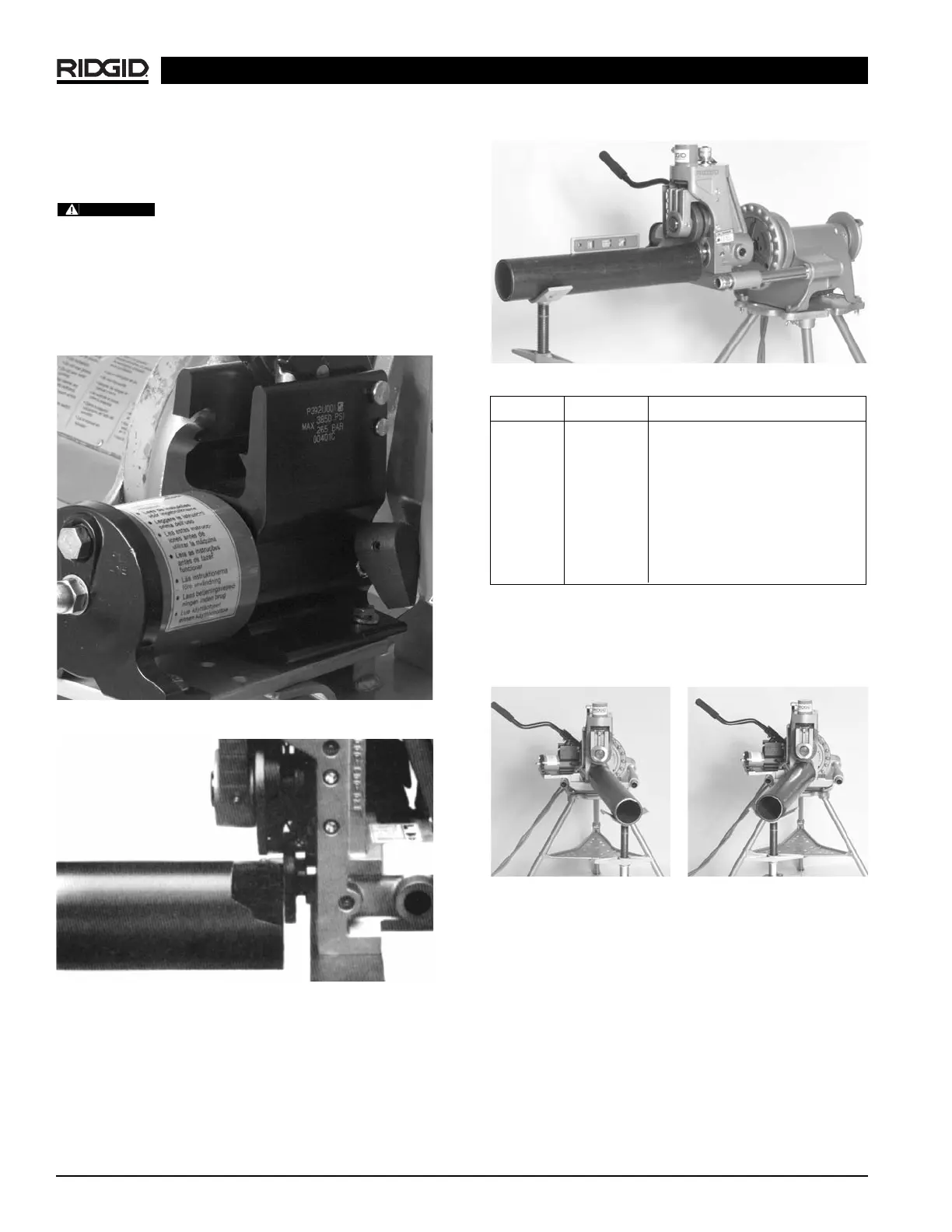
2. Raise upper groove roll housing by placing pump re-
lease lever in RETURN position (away from operator).
(Figure 9)
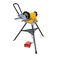
3. Square pipe and pipe support to roll groover making
sure pipe is flush against drive roll flange.
(Figure 10)
Figure 9 – Close-Up of Release Lever on 918 Pump
Figure 10 – Close-Up of Pipe Against Drive Roll Flange
4. Level pipe by adjusting pipe stand.
(Figure 11)
5. Slightly offset pipe and pipe stand (approx.
1
/
2
° away
from or toward operator as directed below:
Figure 11 – Leveling Pipe on Pipe Support and 918
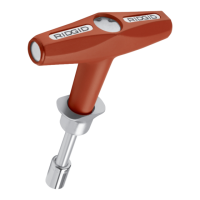
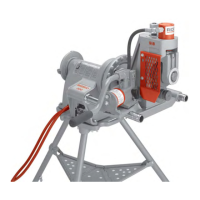
NOTE! If running machine in forward, offset pipe
1
/
2
°
away from operator.
(Figure 12)
NOTE! If running machine in reverse, offset pipe
1
/
2
°
toward operator.
(Figure 13)
Adjusting Roll Groove Depth
NOTE! Due to differing pipe characteristics, a test groove
should always be performed when setting up or
changing pipe sizes. The index depth adjustment
knob must be reset for each diameter of pipe/tube.
1. Advance the upper groove roll by placing the pump re-
lease lever in ADVANCE position (toward operator)
and pump the handle until the upper roll contacts the
pipe to be grooved.
Figure 12 – Offset Pipe on
918 in
FORWARD
Position
Figure 13 – Offset Pipe on
918 in
REVERSE
Position
Mount Setting Degree
300 REV
1
/
2
° toward operator
300 FOR
1
/
2
° away from operator
1822 FOR
1
/
2
° away from operator
1224 REV
1
/
2
° toward operator
1224 FOR
1
/
2
° away from operator
535 REV
1
/
2
° toward operator
535 FOR
1
/
2
° away from operator
WARNING