Used in Conjunction with the Following Power
Drives and Threading Machines
• 300 Power Drive (38 and 57 RPM)
• 535 Threading Machine (38 and 54 RPM)
• 1822 Threading Machine
• 1224 Threading Machine
• 535 Automatic Threading Machine
Standard Equipment
918 Roll Groover Only
• 918 Groover with 2″ – 6″ drive shaft and groove set
•8″ – 12″ Drive shaft and groove set
• Carrying case for drive shaft and groove set
•
1
/
8
″ T-Handle hex wrench (groove roll change out)
• Wrench (drive shaft changeout)
918 Roll Groover Models
Roll Groover Assembly
Instructions
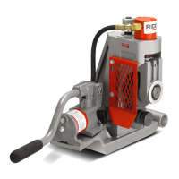
WARNING
The 918 Roll Groover should only be used with the
following power drives and threading machines.
• 300 Power Drive (38 and 57 RPM)
• 535 Threading Machine (38 and 54 RPM)
• 1822 Threading Machine
• 1224 Threading Machine
• 535 Automatic Threading Machine
Use only power drives and threading machines
that operate at 58 RPM or less. Higher speed ma-
chines increase risk of injury.
To prevent serious injury, proper assembly of the
Roll Groover is required. The following procedures
should be followed:
918 Roll Groover
Ridge Tool Company4
Description, Specifications and
Standard Equipment
Description
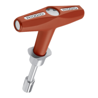
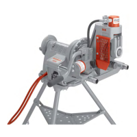
The RIDGID 918 Heavy Duty Roll Groover forms rolled
grooves in steel, stainless steel, aluminum, PVC pipe and
copper tubing. The grooves are formed by the hydraulic
feeding of a grooving roll into the pipe which is sup-
ported by a drive roll.
The 918 Roll Groover includes two (2) groove and drive
shaft sets that can groove the following pipe:
•2″ – 6″ Schedule 10 and 40
•8″ – 12″ Schedule 10 and 8″ Schedule 40
With additional roll sets, the groover can also be adapted
to groove the following:
•2″ – 6″ copper tubing (Types K, L, M, DWV);
•1″ Schedule 10 and 40;
•1
1
/
4
″ – 1
1
/
2
″ Schedule 10 and 40.
The 918 Heavy Duty Roll Groover is specifically designed
for use with the RIDGID 300 Power Drive, as well as
RIDGID 535, 535A, 1822, and 1224 Threading Machines.
Different mounting kits are required for each power source.
When properly used, the Model 918 makes
grooves that are dimensionally within the specifications of
AWWA C606-87. Selection of appropriate materials and
joining methods is the responsibility of the system de-
signer and/or installer. Before any installation is attempted,
careful evaluation of the specific service environment, in-
cluding chemical environment and service temperature,
should be completed.
Specifications
Roll Grooving Capacity
(See Table II for wall thickness)
•1″ – 12″ Schedule 10
•1″ – 8″ Schedule 40
•2″ – 6″ Copper types K, L, M, DWV
•2″ – 8″ Schedule 40 PVC
Do not use to groove 8″ schedule 40 steel
pipe harder than 150 BHN. Doing so may result in im-
properly formed grooves that do not meet required
specifications.
Depth Adjustment ..........Indexed adjustment knob
Actuation ........................Hydraulic hand pump
CAUTION
Catalog Model Weight
No. No. Description lb. kg.
48297 918-1 918 Roll Groover w/300 Power Drive Mount Kit 81 36,7
48377 918-2 918 Roll Groover w/1822 Carriage Mount Kit 81 36,7
48382 918-4 918 Roll Groover w/1224 Carriage Mount Kit 81 36,7
48387 918-5 918 Roll Groover w/535 Carriage Mount Kit 81 36,7
47222 918 Only 918 Roll Groover Only 75 34,0
Mounting Kit Only
48292 911 300 Power Drive Mount Kit Only 9 4
48392 912 1822 Carriage Mount Kit Only 39 17,7
48397 914 1224 Carriage Mount Kit Only 36 16,4
48402 915 535 Carriage Mount Kit Only 22 10
CAUTION