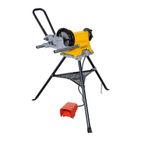
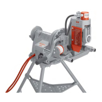
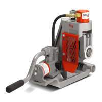
918 Roll Groover
Ridge Tool Company16
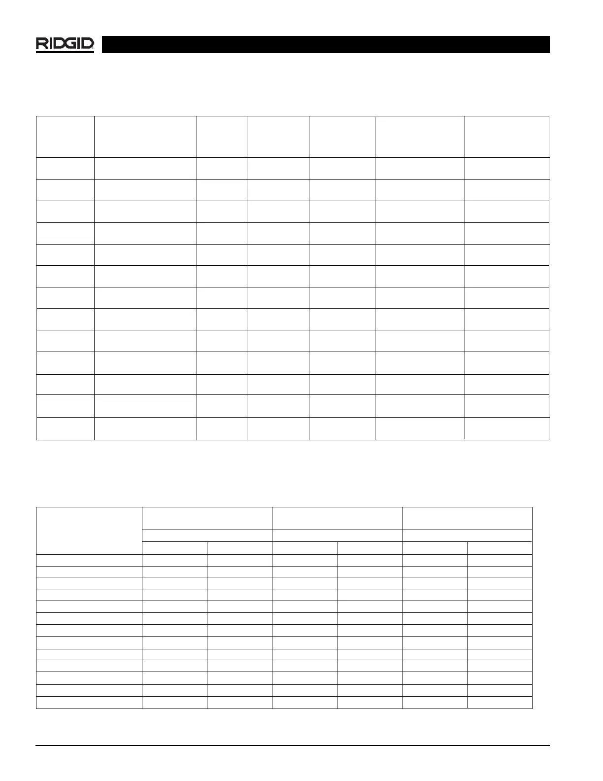
Table II. Pipe Maximum and Minimum Wall Thickness
NOTE! All Dimensions are in Inches.
CARBON STEEL OR STAINLESS STEEL
ALUMINUM PIPE OR TUBE PIPE OR TUBE PVC PIPE
Pipe Size
Wall Thickness Wall Thickness Wall Thickness
Min. Max. Min.
Max. Min. Max.
1″ .065 .133 .065 .109 .133 .133
1
1
/
4
″ .065 .140 .065 .140 .140 .140
1
1
/
2
″ .065 .145 .065 .145 .145 .200
2″ .065 .154 .065 .154 .154 .154
2
1
/
2
″ .083 .203 .083 .188 .203 .276
3″ .083 .216 .083 .188 .216 .300
3
1
/
2
″ .083 .226 .083 .188 .226 .318
4″ .083 .237 .083 .188 .237 .337
5″ .109 .258 .109 .188 .258 .258
6″ .109 .280 .109 .188 .280 .280
8″ .109 .322 .109 .188 .322 .322
10″ .134 .165 .134 .188 — —
12″ .156
.180 .156 .188 — —
CAUTION: Do not use to groove 8″ schedule 40 steel pipe harder than 150 BHN. Doing so may result in improperly formed grooves that do not meet
required specifications.
TA B C D
NOM. PIPE MIN. GASKET GROOVE GROOVE NOM.
PIPE DIAMETER WALL SEAT WIDTH DIAMETER GROOVE
SIZE O.D. TOL. THK. +.015/-.030 +.030/-.015 O.D. TOL. DEPTH (Ref. #2)
1 1.315 +.013 .065 .625 .281 1.190 +.000 .063
-.013 -.015
1
1
/
4
1.660 +.016 .065 .625 .281 1.535 +.000 .063
-.016 -.015
1
1
/
2
1.900 +.016 .065 .625 .281 1.775 +.000 .063
-.016 -.015
2 2.375 +.024 .065 .625 .344 2.250 +.000 .063
-.016 -.015
2
1
/
2
2.875 +.030 .083 .625 .344 2.720 +.000 .078
-.018 -.015
3 3.50 +.030 .083 .625 .344 3.344 +.000 .078
-.018 -.015
3
1
/
2
4.00 +.030 .083 .625 .344 3.834 +.000 .083
-.018 -.015
4 4.50 +.035 .083 .625 .344 4.334 +.000 .083
-.020 -.015
5 5.563 +.056 .109 .625 .344 5.395 +.000 .084
-.022 -.015
6 6.625 +.050 .109 .625 .344 6.455 +.000 .085
-.024 -.015
8 8.625 +.050 .109 .750 .469 8.441 +.000 .092
-.024 -.020
10 10.75 +.060 .134 .750 .469 10.562 +.000 .094
-.025 -.025
12 12.75 +.060 .156 .750 .469 12.531 +.000 .110
-.025 -.025
Table I. Standard Roll Groove Specifications
1
NOTE! All Dimensions are in Inches.
1. As per AWWA C606-87.
2. Nominal Groove Depth is provided as a reference dimension. Do not use groove depth to determine groove acceptability.
NOTE! Fitting manufacturer’s recommendations should be followed regarding maximum allowable flare diameters.

 Loading...