918 Roll Groover
Ridge Tool Company6
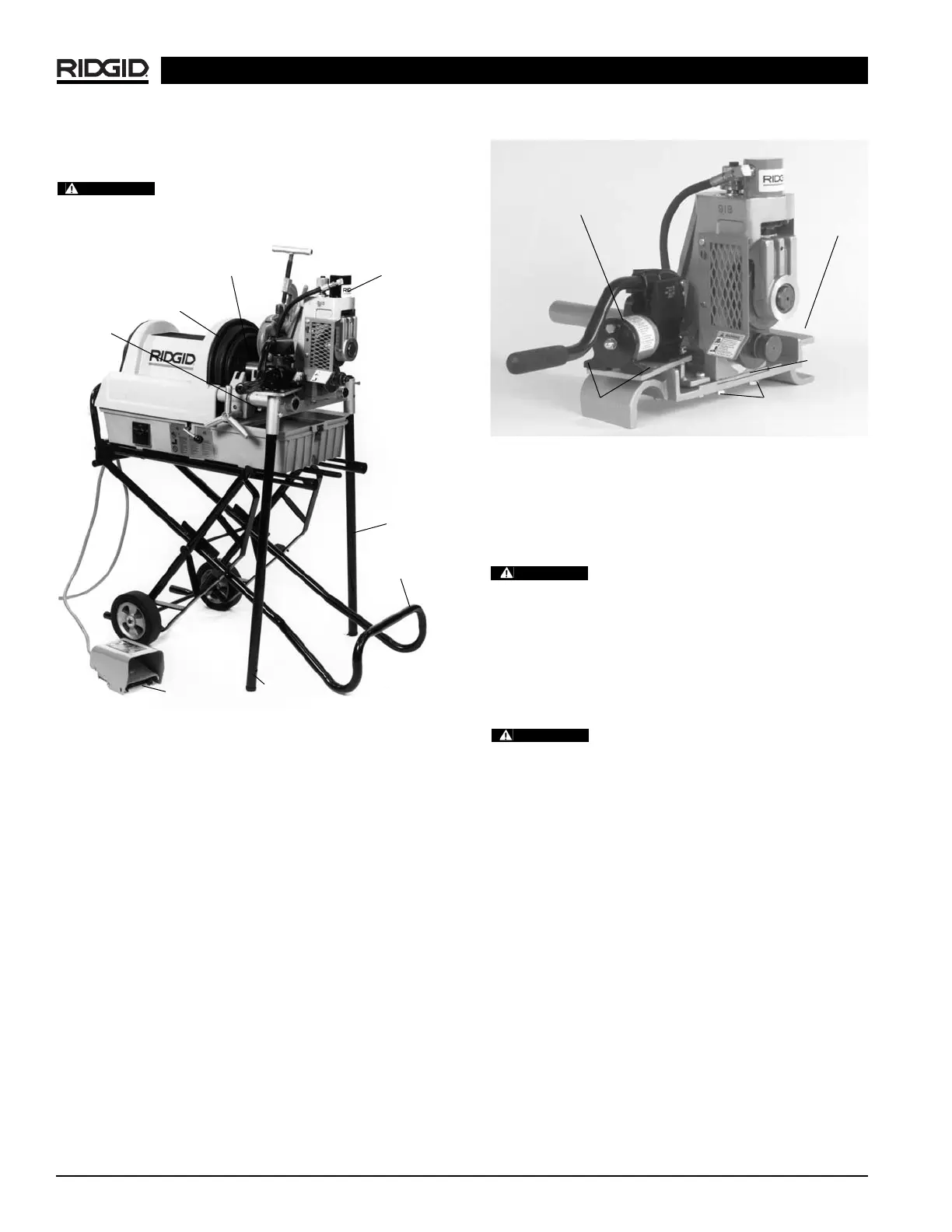
NOTE! Support legs are not needed when when using
these stands.
Drive bar must be centered in front chuck
jaws. All bolts must be tight and the drive bar must be
securely held in chuck when closed.
Figure 4 – 918 Roll Groover Mounted on 1822 with 1406
Stand
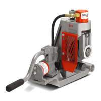
Installing the 918-4 Roll Groover on the
1224 Threading Machine
Sub-Assembly
1. Align housing plate in recessed area of 1224.
2. Align 918 on the 1224 mounting base.
(Figure 5)
3. Install and tighten the (2)
1
/
2
″ x 1
1
/
4
″ hex bolts which
connect the 918 to mounting base.
4. Attach pump bracket with the two (2)
3
/
8
″ x
1
/
2
″ hex
bolts.
5. Position hydraulic pump and securely bolt in place
with (4)
1
/
4
″ x
3
/
4
″ hex bolts.
6. Attach drive bar adapter to roll groover by tightening
(2) set screws.
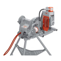
Figure 5 – 918 Heavy Duty Roll Groover on 1224
Threading Machine Mounting Base
Installing on 1224 Threading Machine
1. Position carriage towards front chuck and swing car-
riage tools to rear position.
Position reamer inside the die head to
prevent accidental contact.
2. Place 918-4 on the far side carriage rail and lower
onto near side rail.
(Figure 6)
3. Position base so that the drive bar feeds into the
open chuck.
4. Tighten chuck jaws securely into drive bar.
Drive bar must be centered in front chuck
jaws. All bolts must be tight and the drive bar must be se-
curely held in chuck.
Front Chuck
Foot Switch
Drive Bar
Carriage
918-2
Sub-assembly
Hydraulic Pump
1224
Mounting
Base
1
/
4
″ x
3
/
4
″ bolts (4)
for mounting
hydraulic pump
1
/
2
″ x 1
1
/
4
″ bolts (2)
for mounting base
Support
Leg
Support
Leg
WARNING
1406
Stand
Housing
Plate
CAUTION
WARNING