HELIOTERM INVERTER
2
A
D
E
C
H
B
G
M
F
I
L
B
C
D
A
Vista dal basso / Bottom view
Doc-0091334 Rev. 0
PT
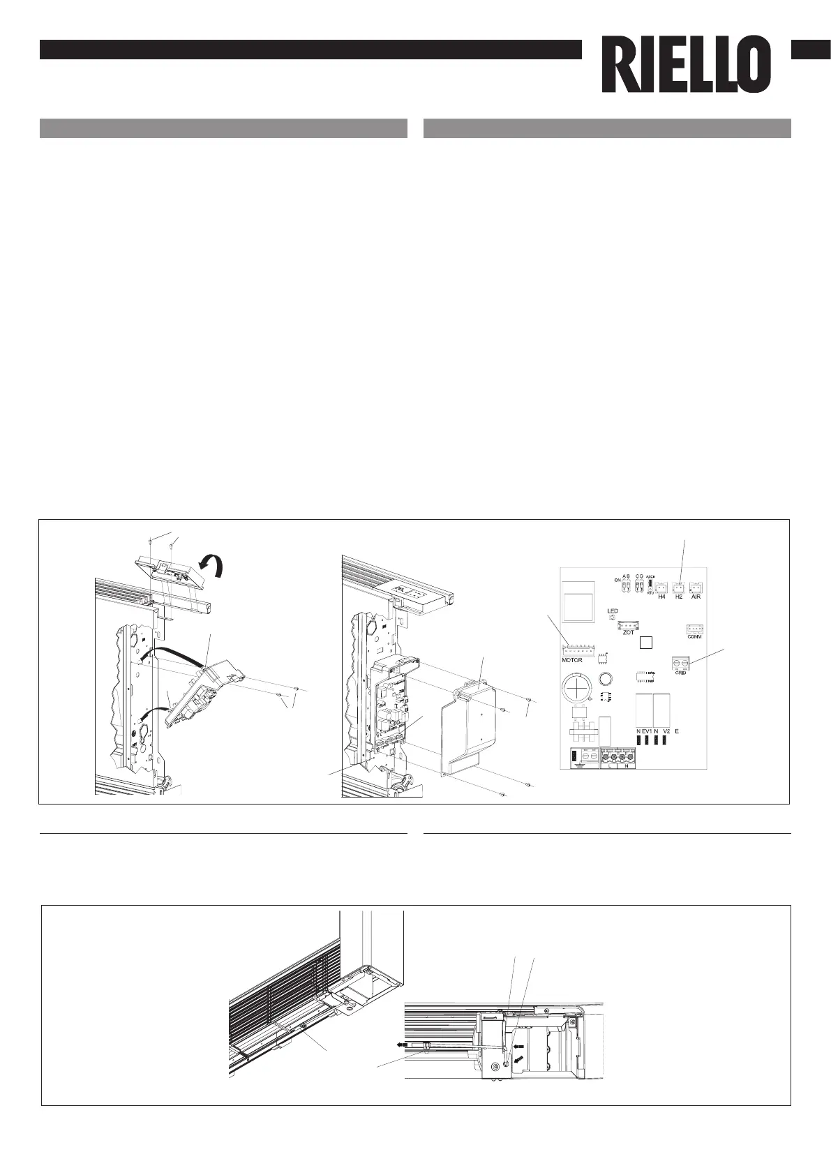
outras versões, remova a ponte e ligue os dois terminais
provenientes do microinterruptor de segurança da grelha*.
ligue o conector da sonda de água (H2) presente no
aparelho. A sonda de temperatura da água controla a
temperatura dentro das baterias e determina o arranque do
ventilador com base nos parâmetros predenidos (funções
de temperatura mínima de inverno e de temperatura
máxima de verão**). Verique se está corretamente
inserida na cavidade presente na bateria.
efetue as ligações elétricas (
consulte também o parágrafo
“Montagem da sonda de temperatura do ar”
), organize
as cablagens, xe os cabos com ajuda das 3 forquilhas
fornecidas (ref.G);
feche a caixa, xando os 4 parafusos (ref.H);
volte a montar o painel lateral estético do aparelho;
aperte o parafuso superior no painel de controlo;
coloque as tampas dos parafusos no respetivo alojamento
no painel de controlo;
* Para versões com ligações hidráulicas à direita, consulte o
respetivo parágrafo.
** Se, após a ligação, a placa detetar a sonda H2, o
arranque ocorre em condições normais com funções de
temperatura mínima e máxima. A placa prevê também o
funcionamento sem sonda H2, nesse caso, os limites de
paragem do ventilador são ignorados.
Montagem da sonda de temperatura do ar
Para posicionar a sonda de temperatura (ref.A):
passe a sonda através do furo do ombro (ref.B)
insira a sonda no furo inferior (ref.C)
xe a sonda no respetivo engate (ref.D).
EN
The other versions remove the jumper and connect the
two terminals from the grid safety microswitch*.
connect the water probe connector (H2) on the Cooler-
convector/cooler-radiator; the water temperature
probe checks the temperature inside the batteries
and determines the start of the fan based on the set
parameters (minimum winter and maximum summer
functions**). Check that it is inserted correctly in the
well on the battery;
make the electrical connections (see also section
“Mounting air temperature sensor”), order the wiring
and x the wires using the 3 supplied clamps (ref. G);
close the box and x with the 4 screws (ref. H);
mount the aesthetic side panel on the Cooler-convector/
cooler-radiator;
tighten the upper screw on the control panel;
place the screw cover into the slot on blind panel;
* For versions with hydraulic connections on the right
refer to the relevant paragraph.
** If after powering the equipment the board detects the
H2 probe, the start-up will take place under normal
conditions with minimum and maximum functions.
The board can also operate without a H2 probe, case in
which the fan stop thresholds will be ignored.
Mounting air temperature probe
To position the temperature probe (ref. A):
pass the probe through the hole on the shoulder (ref. B)
insert the probe in the lower hole (ref. C)
x the probe in the special hook (ref. D).
Vista do fundo / Bottom view
 Loading...