INSTALLATION
34
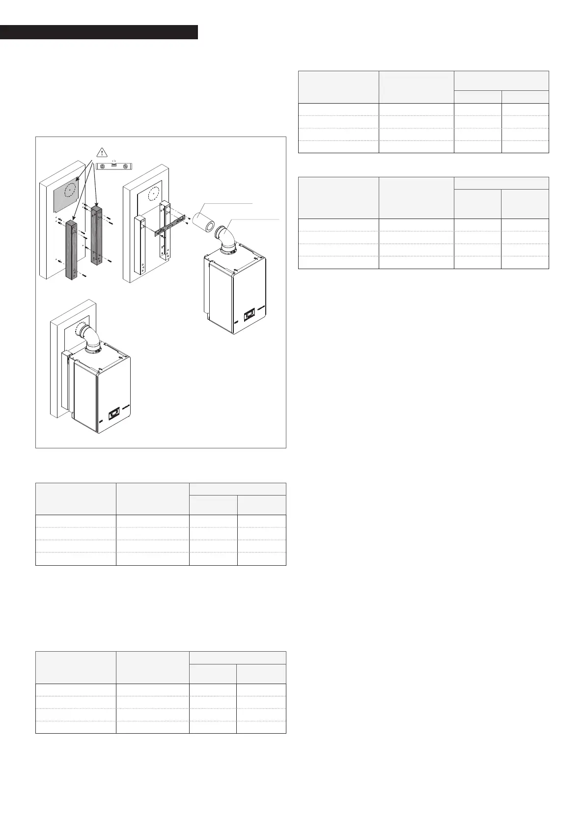
Ø 80-125 CURVE INSTALLATION on CONDEXA HPR 55-70
For this type of installation it is necessary to use the spa-
cer kit for wall xing, available on request.
Prepare the assembly by positioning the ue exhaust car-
dboard template, the spacers and the xing crosspiece as
shown in the gure.
Complete the installation using the bend and extension
Ø 80-125 available as an accessory in the Riello catalog.
BEND 90° Ø80/125 PP/Met
EXTENSION Ø80/125 PP/Met
TYPE “B” INSTALLATION
Discharge Ø 80 mm
Model
Maximum
length
Ø 80 mm
Pressure loss
bend 45° bend 90°
Condexa HPR 35 48 m 1 m 1,5 m
Condexa HPR 45 33 m 1 m 1,5 m
Condexa HPR 55 17 m 1 m 1,5 m
Condexa HPR 70 13 m 1 m 1,5 m
With type B installation, the combustion air is taken
from the room and delivered via the openings made on
the rear panel of the appliance, which must be located
in a suitable utility room that is well-aired.
TYPE “C” INSTALLATION
Concentric pipes Ø 80-125 mm
Model
Maximum
length
Ø 80-125 mm
Pressure loss
bend 45° bend 90°
Condexa HPR 35 25 m 1 m 1,5 m
Condexa HPR 45 25 m 1 m 1,5 m
Condexa HPR 55 10 m 1 m 1,5 m
Condexa HPR 70 10 m 1 m 1,5 m
Concentric pipes ø 60-100mm
Model
Maximum
length
Ø 60-100 mm
Pressure loss
bend 45° bend 90°
Condexa HPR 35 10 m 1,3 m 1,6 m
Condexa HPR 45 10 m 1,3 m 1,6 m
Condexa HPR 55 - 1,3 m 1,6 m
Condexa HPR 70 - 1,3 m 1,6 m
Separated pipes Ø 80 mm + Ø 80 mm
Model
Maximum
length
Ø 80+80 mm
Pressure loss
bend 45° bend 90°
Condexa HPR 35 30+30 m 1 m 1,5 m
Condexa HPR 45 21+21 m 1 m 1,5 m
Condexa HPR 55 12+12 m 1 m 1,5 m
Condexa HPR 70 10+10 m 1 m 1,5 m
9
Do not install the ue gas exhaust near ammable
or plastic materials, whose characteristics can be
changed in the presence of high temperatures.
9
The straight length is intended without bends, and
includes the terminals and joints.
9
The boiler is supplied without the ue gas/air suc-
tion kit, as it is possible to use the accessories for
condensing appliances best suited to the installation
characteristics (refer to the catalogue).
9
In the case of use of non-original ue gas exhaust
and air intake ducts, the use of certied ducts com-
pliant with the appliance to which they are connected
must still be guaranteed, with a temperature class
≥120°C and resistant to condensation.
9
To ensure the best installation safety, attach the pipes
to the wall (or ceiling) using specic xing brackets
positioned in line with each joint (at a distance such
that the length of each single extension is not exceed-
ed) and immediately before and after every change of
direction (bend).
9
The maximum pipe length values refer to the ue pipe
accessories available in the catalogue.
9
It is compulsory to use specic pipes.
9
The non insulated ue gas outlet pipes are potential
sources of danger.
9
The use of a longer pipe causes a loss of output of the
boiler.
9
The exhaust pipes can face in the direction most suit-
ed to the installation requirements.
9
As envisaged by current legislation, the boiler is de-
signed to take in and dispose of ue gas condensate
and/or rainwater condensate deriving from the ue
gas discharge system via its own drain-trap.
9
If a condensate relaunch pump is installed, check the
technical output data (provided by the manufacturer)
to ensure it works properly.
 Loading...