1541
5
GB
NOTE:
The burner is provided with a socket for the direct electrical connection to the boiler’s plug
(see diagram at page 4)
. Should the boiler be without plug, it is then necessary:
– remove the socket and respective cable mounted on the burner;
– carry out the electrical connection direct to the wiring terminal block of the burner as shown on
the diagram below.
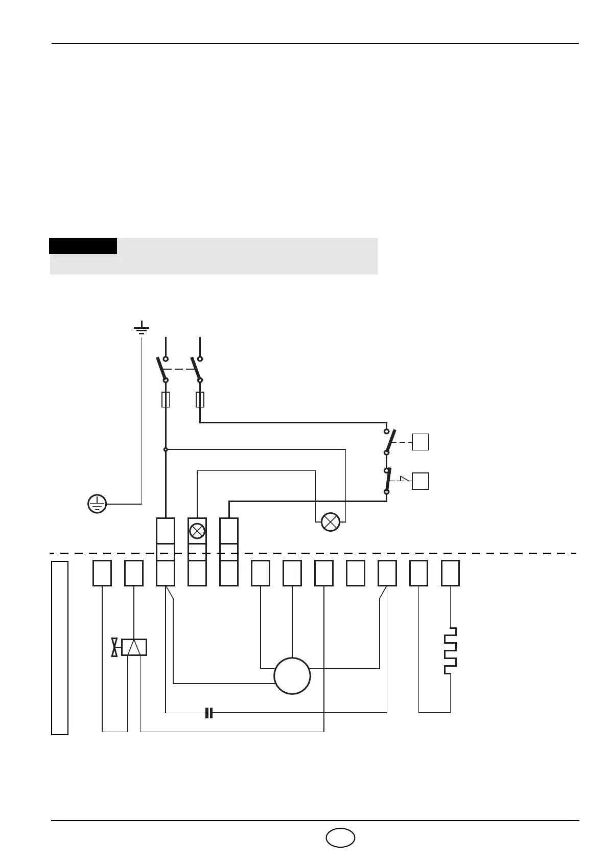
BURNER ELECTRICAL WIRING
Brown
1 2 3 4 5 6 7 8 9
Terminal block of
control-box
531SE
*
Red
Red
11 10 12
Heater 55W
WARNING
DO NOT EXCHANGE THE NEUTRAL WITH THE PHASE
White (50V)
Blue
Motor
Capacitor
Regulating thermostat
Neutral
Switch with fuse
6A max.
N L
M
~
Black
230V ~ 50Hz
N L
Limit thermostat
with manual resetting
Remote lock-out lamp
(230V - 0.5A max.), if required
Blue
Brown
Valve
T
T
D5498
Black
CARRIED-OUT IN THE FACTORY
NOTES:
– Wires of 1 mm
2
section.
– The electrical wiring carried out by the
installer must be in compliance with the
rules in force in the Country.