2837
2
GB
➤
Re-assemble everything following the above in-
structions in reverse order (see fig. 4).
ATTENTION
When the nozzle-holder assembly is re-
assembled, tighten the nut (1) with a torque of
15 Nm, as shown in the figure below.
➤
Replace the control box and tighten the screw (A, fig. 1 page 1) with a torque of 1 - 1.2 Nm.
➤
Connect all the components to the control box as shown in the wiring diagram on page 3.
➤
Stick the specification label next to the one already on the appliance.
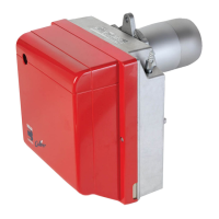
TECHNICAL DATA
WORKING FIELD
(as EN 267)
TYPE 364T1
Output - Thermal power 1.7
–
5 kg/h - 20
–
60 kW
Fuel Light oil, viscosity 4 –
6 mm
2
/s at 20 °C
Electrical supply Single phase,
~
50Hz 230V
±
10%
Motor Run current 0.85A – 2750 rpm – 289 rad/s
Capacitor 4
µ
F
Ignition transformer Secondary 8 kV – 16 mA
Pump Pressure: 8
–
15 bar
Absorbed electrical power 0.29 kW
Fig. 4
S7746
1
TIGHTEN WITHOUT MOVING
BACKWARDS TO THE END
D5684
2 3 Light oil output – kg/h
20 30 40 Thermal power – kW
0.8
0.6
0.4
0.2
0
Pressure in combustion
chamber – mbar
D5535
4
50
5
60
1.4
1.7
 Loading...