18
ENGLISH
See Fig. 25
b
For the minimum distances from combustible materials, see what
is reported in Fig. 27
See Fig. 27
3.4 Evacuating products of combustion
3.4.1 Models for indoor installation
For ue gas discharge, refer to Standards UNI 7129-7131. The ue gas
exhaust/air intake kit is not supplied with the boiler as accessories for
sealed-chamber forced-draught appliances, which better adapt to the in
-
stallation context, can be used.
To
extract the ue gases and restore the combustion air in the boiler,
use original piping or others with the same characteristics which are EC
certied and ensure that they are correctly connected as indicated in the
instructions provided with the ue gases accessories.
A single ue can be connected to several appliances provided that every
appliance is sealed chamber type.
The boiler is a type C appliance (with a sealed chamber) and must there
-
fore have a secure connection to the ue gases exhaust pipe and com-
bustion air intake pipe which both ow outside, and without which the
appliance cannot operate.
“FORCED OPEN” INST
ALLA
TION (B22-B52)
The ue gas exhaust pipe can be directed to the most suitable direction
according to installation requirements.
For installation, follow the instructions supplied with the kit.
In this conguration, the appliance is connected to the ø 80 mm ue gas
exhaust pipe by means of a ø 60-80 mm adaptor (Fig. 28).
b
In this conguration the combustion air is withdrawn from the room
where the appliance is installed, which should be technically suita-
ble and ventilated.
b
The non insulated ue gas outlet pipes are potential sources of
danger.
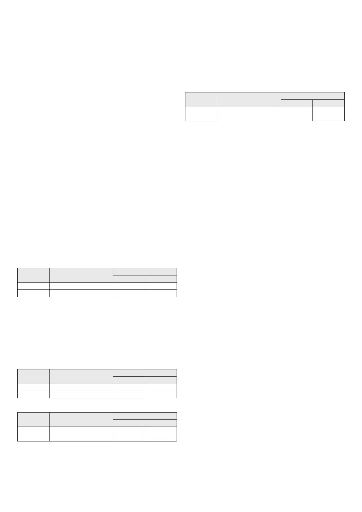
b
The table indicates the permitted linear lengths.
Model
Maximum length
Ø 80 mm (m)
Loss of load (m)
45° bend 90° bend
11-13 15 1,2 1,7
17 6 1,2 1,7
See Fig. 28
COAXIAL DISCHARGES (60-100 Ø)
The boiler has been designed to be connected to concentric discharge/
suction pipes and with the opening for air suction (
D
) closed (Fig. 29).
Coaxial outlets can be pointed in the direction most suited to the specic
installation room, in line with the lengths shown in the table.
For installation, follow the instructions supplied with the kit.
b
The table indicates the permitted linear lengths.
Horizontal
Model
Maximum length
Ø 60-100 mm (m)
Loss of load (m)
45° bend 90° bend
11-13 3,5 1 1,5
17 2,6 1 1,5
Vertical
Model
Maximum length
Ø 60-100 mm (m)
Loss of load (m)
45° bend 90° bend
11-13 4,5 1 1,5
17 3,6 1 1,5
See Fig. 29
SPLIT PIPE OUTLETS (80 Ø)
Twin outlets can be placed in the most suitable direction according to the
room requirements.
The combustion air intake pipe must be chosen from the two inlets (
E
and
F
); remove the closure plug xed with screws and use the specic adaptor
for the chosen input.
The air inlet adaptor Ø 80 (
E
) must be oriented correctly, so it must be
xed with the relative screws, so that the positioning tab does not interfere
with the casing.
b
The table indicates the permitted linear lengths.
Model
Maximum length
Ø 80 mm (m)
Loss of load (m)
45° bend 90° bend
11-13 15+15 1,2 1,7
17 6+6 1,2 1,7
See Fig. 30 and Fig. 31
The gures Fig. 32 and Fig. 33 show the water heater from above with the
reference positions for the ue gas exhaust and combustion air inlet, with
respect to the water heater support plate.
3.4.2 Models for outdoor installation
For information on evacuating the products of combustion, please refer
to UNI 7129.
The appliance is type A2 and therefore has no pipes for discharging ue
gases or a suction line for combustion air.
The combustion gases are expelled directly into the air by the integrated
outlet.
See Fig. 34
a
Avoid inhaling combustion gases.
a
Avoid direct contact with the combustion gases since they can
reach extremely high temperatures that can cause burns.
a
Avoid direct contact with the discharge since it can reach extremely
high temperatures that can cause burns.
a
To ensure the combustion gases are expelled correctly, it is forbid-
den to obstruct or cover (even just partially) the discharge outlet.
a
It is forbidden to loiter near the appliance when it is operating.
3.5 Electrical connections
Connect the cable supplied to the line, respecting the phase, neutral and
earth wiring. Should the power cable need to be replaced, this must be
carried out by a qualied technician. Connect the appliance to a H03V2
V2-F (3 x 0.75 mm
2
) max 7 mm Ø cable such as the one supplied; the
ground wire must also be 30 mm longer that the power cables. Power
to the appliance via an omnipolar switch with a gap of at least 3 mm
between contacts. For maintenance operations, cut the voltage by using
the omnipolar switch.
b
We decline all responsibility for damage to persons, animals or
objects deriving from the failure to earth the appliance or wire an
electrical system that complies with the standards in force.
A qualied professional should check that the electrical system is suitable
for the appliance’s maximum absorbed output, as shown on the plate,
ensuring particularly that the section of the system cables is suited to the
appliance’s absorbed power.
Adaptors, multiple sockets or extensions should not be used to connect
the appliance to the main power supply.
 Loading...