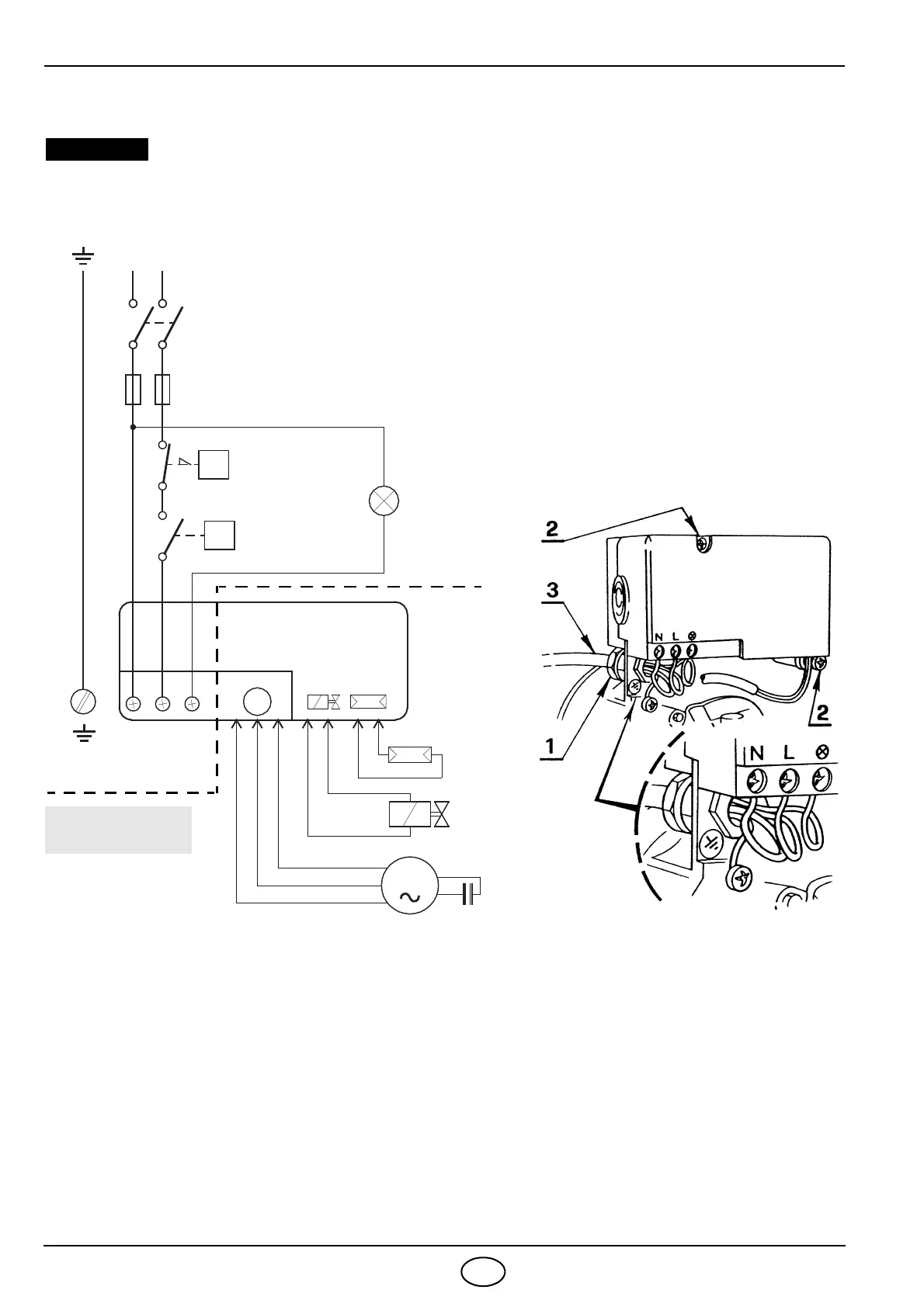
Do not exchange the neutral with the phase.
CARRIED-OUT
230V
~
50Hz
L
Main switch
T6A
Safety thermostat
Limit thermostat
Remote lock-out signal
(230V - 0.5A max.)
Photoresistance
Oil valve
Capacitor
Burner-earth
M
Black
White
Blue
NL
M
N
Motor
Blue
Brown
T
T
CONTROL BOX
535SE
IN THE FACTORY
Fig. 8
S7031
ELECTRICAL CONNECTIONS
– Remove the protection crankcase (8,
fig. 1, page 1) after removing the 3
retainer screws. Widen the upper slit
and remove the protection crankcase,
inserting the oil pipe and the flexible oil
lines.
– Insert PG 13.5 cable-gland (1, fig. 8)
into the wire access hole and tighten it
with the nut.
– Insert the electrical cable into the con-
nector and make electrical connections
as shown in fig. 8.
– Put the protection crankcase back in
place.
NOTES
– Wires of 1 mm
2
section.
– The electrical wiring carried out by the installer must be
in compliance with the rules in force in the Country.
TESTING
Check the shut-down of the burner by opening the
thermostats and the lock-out by darkening the pho-
toresistance.
To remove the control box from the
burner proceed as follows:
– Take out the photoresistance (2, fig. 9,
page 5).
– Remove the nozzle holder assembly
(see fig. 9, page 5).
– Remove the protection crankcase (8,
fig. 1, page 1), as above mentioned.
– Disconnect the main voltage cable (3,
fig. 8).
– Remove screws (2, fig. 8) and discon-
nect wires of motors, photoresistance
and coil.
D5259