2518
5
GB
4. WORKING
4.1 COMBUSTION ADJUSTMENT
In conformity with Efficiency Directive 92/42/EEC the application of the burner on the boiler, adjustment and
testing must be carried out observing the instruction manual of the boiler, including verification of the CO and
CO2 concentration in the flue gases, their temperatures and the average temperature of the water in the boiler.
To suit the required appliance output, choose the proper nozzle and adjust the pump pressure, the setting
of the combustion head, and the air damper opening in accordance with the following schedule.
The values shown in the table are measured on a CEN boiler (as per EN 267). They refer to 12.5% CO
2
at
sea level and with light oil and room temperature of 20°C.
4.2 RECOMMENDED NOZZLES:
Delavan type W -B ; Danfoss type S - B;
Monarch type R ; Steinen type S - Q.
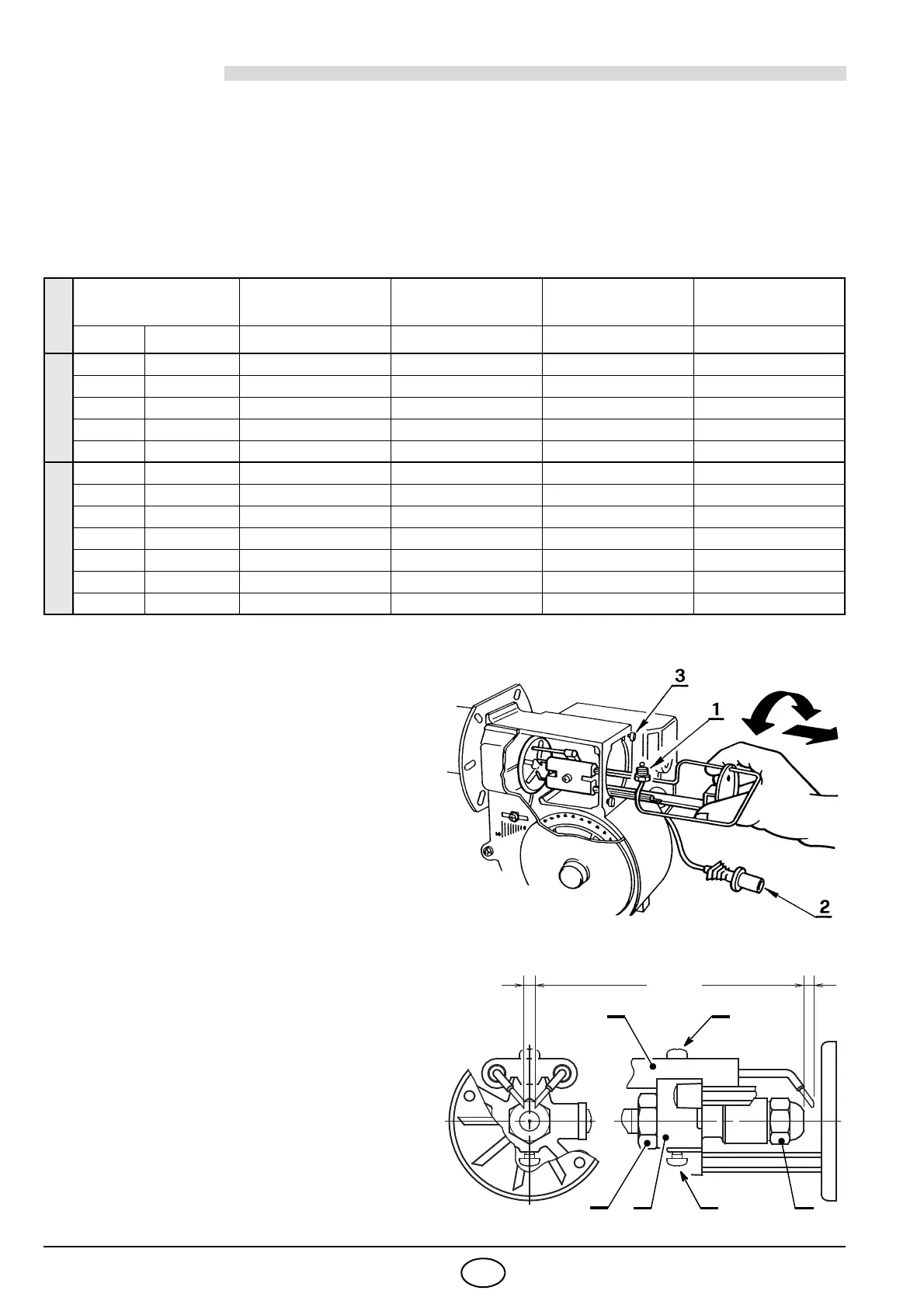
To reach the nozzle, the diffuser-disc assem-
bly and the electrodes, proceed as follows:
(see fig. 9 and 10)
– Disconnect the oil pipe fitting (1) from the
pump. Take out the photoresistance (2),
loosen the retainer screws (3) of the cover.
– Remove the nozzle holder assembly after
turning and sliding it out. The nozzle holder
assembly must stay on the left side of the
burner during its sliding.
– Remove the diffuser-disc assembly (4) from
the nozzle holder (5) after loosening the
screw (6).
– Insert the proper nozzle (9) into the nozzle
holder and tighten securely.
– Replace the diffuser-disc assembly (4) and
insert it in the nozzle holder (5) until the end.
Lock with screw (6).
4.3 ELECTRODES ADJUSTMENT
Loosen the screw (7), move the electrodes
assembly (8) and lock the screw (7), (see fig. 10).
TYPE
Nozzle
Pump
pressure
Burner
output
Comb. head
adjustment
Air damper
adjustment
GPH Angle bar kg/h ± 4% Set-point Set-point
721 T
0.50 80° 10 1.8 0.5 1.5
0.50 80° 12 2.0 1.0 2.0
0.60 60°/80° 12 2.4 2.0 4.0
0.65 60°/80° 12 2.6 2.5 4.5
0.75 60° 13 3.2 4.0 6.5
722 T
0.60 80° 11 2.3 0.5 2.5
0.65 60° 12 2.6 1 3.5
0.75 60° 12 3.0 1.5 3.5
0.85 60° 12 3.4 2.5 5.0
1.00 60° 12 4.0 3 7.5
1.10 60° 12 4.4 4 9.5
1.25 60° 12 5.0 4 10.0
S7030
4.5 – 0.5 mm
0
2 – 2.5 mm
5
4
7
6
9
8
D5268
Fig. 10
Fig. 9
 Loading...