2518
6
GB
4.4 PUMP PRESSURE
The pump leaves the factory set at 12 bar.
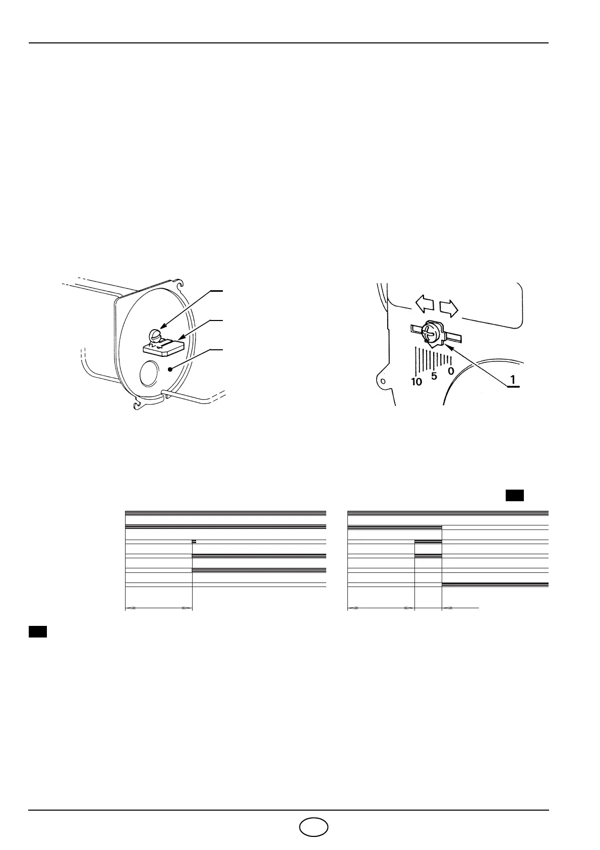
4.5 COMBUSTION HEAD SETTING (see fig. 11)
It depends on the output of the burner and is carried out by rotating clockwise or counterclockwise the set-
ting screw (1) until the set-point marked on the regulating rod (2) is level with the outside plane of the noz-
zle holder assembly (3).
4.6 AIR DAMPER ADJUSTMENT (see fig. 12)
Loosen the screw (1) and move the indicator towards the required set-point and then lock the screw (1).
4.7 BURNER START-UP CYCLE
Lock out is indicated by a lamp on the control box (5, fig. 1, page 1).
S7032
1
2
3
Fig. 11
S7033
Fig. 12
Lock-out due to failure to light
Normal
D5029
~ 12s
Thermostat
Motor
Ignition transformer
Valve
Flame
Lock-out lamp
~ 12s 5s
 Loading...