20168481
20
Installation
5.8 Nozzle installation
The burner complies with the emission requirements of the EN
267 standard. In order to guarantee that emissions do not vary,
recommended and/or alternative nozzles specified by Riello in
the Instruction and warning booklet should be used.
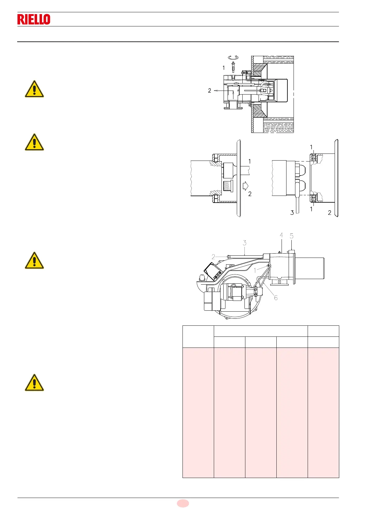
Remove the screw 1) and the internal part 2)(Fig. 15).
Assemble the two nozzles with the socket spanner 1)(A-
Fig. 16) (16mm), after removing the plastic plugs 2)(A-
Fig. 16), passing from the central opening of the flame
stability disc. Alternatively, loosen the screws 1)(B-Fig. 16),
remove the disc 2)(B-Fig. 16), and replace the nozzles using
the spanner 3)(B-Fig. 16).
The nozzle for the 1st stage of operation is the one beneath
the ignition electrodes, Fig. 14 on page 19.
Reassemble the burner on the guides 3)(Fig. 17) at about
100 mm from the pipe coupling 4), burner in the position
shown in Fig. 11 on page 18;
insert the electrode cables and then slide the burner up to
the pipe coupling, the burner in the position indicated in
Fig. 17;
refit screws 2)(Fig. 17) on slide bars 3);
fix the burner to the pipe coupling with the screws 1);
reconnect the light oil pipes by screwing the two fittings
6)(Fig. 11 on page 18).
5.8.1 Recommended nozzle
Both nozzles must be chosen from among those listed in Tab. H.
The first nozzle determines the delivery of the burner in the 1st
stage.
The second nozzle works together with the 1st nozzle to
determine the delivery of the burner in the 2nd stage.
The deliveries of the 1st and 2nd stages have to be within the
value range indicated Tab. A on page 8.
Use nozzles with a 60° spray angle at the recommended
pressure of 12 bar.
In general both nozzles have the same delivery.
Tab. H
It is advisable to replace the nozzle once a year
during periodical maintenance.
The use of nozzles other than those specified by
Riello S.p.A. and inadequate regular maintenance
may result into emission limits non-conforming to
the values set forth by the regulations in force, and
in extremely serious cases, into potential hazards
to people and objects.
The manufacturing Company shall not be liable
for any such damage arising from non-
observance of the requirements contained in this
manual.
Do not use any sealing products such as:
gaskets, tape or sealants.
Be careful to avoid damaging the nozzle
sealing seat.
The nozzle must be screwed into place tightly
but not to the maximum torque value
provided by the wrench.
On closing the burner on the two guides it is
advisable to gently pull the high voltage wires
outwards until they are under slight tension.
GPH
Kg/h kW
10 bar 12 bar 14 bar 12 bar
5.00
5.50
6.00
6.50
7.00
7.50
8.00
8.30
8.50
9.00
9.50
10.0
10.5
11.0
12.0
12.3
13.0
13.8
14.0
15.0
15.3
16.0
17.0
19.2
21.1
23.1
25.0
26.9
28.8
30.8
31.9
32.7
34.6
36.5
38.4
40.4
42.3
46.1
47.3
50.0
53.1
53.8
57.7
58.8
61.5
65.4
21.2
23.3
25.5
27.6
29.7
31.8
33.9
35.2
36.1
38.2
40.3
42.4
44.6
46.7
50.9
52.2
55.1
58.5
59.4
63.6
64.9
67.9
72.1
23.1
25.4
27.7
30.0
32.3
34.6
36.9
38.3
39.2
41.5
43.8
46.1
48.4
50.7
55.3
56.7
59.9
63.3
64.5
69.2
70.5
73.8
78.4
251.4
276.3
302.4
327.3
352.3
377.2
402.1
417.5
428.2
453.1
478.0
502.9
529.0
553.9
603.7
619.1
653.5
693.8
704.5
754.3
769.7
805.3
855.1
 Loading...


