11
Shackmaster™ Power 500 DC Power Supply Instruction Manual
Installation
Two 5V USB Type A and two 5V USB Type C connectors are at the bottom-left corner
of the front panel and can be used for charging.
The Anderson Powerpole
®
Connectors are at the bottom-left corner.
The loads can be connected also to Anderson Powerpole
®
connectors at the rear panel.
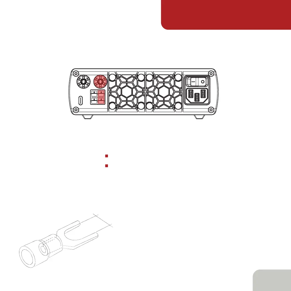
There are additional connectors at the rear panel of the power supply:
one USB Type C connector for PC connection
1x Binding 13.8V post
Anderson Powerpole
®
and Binding posts are color coded as:
Red - + (plus 13.8V), Black - - (minus 13.8V)
It is recommended to connect the load to
the binding posts by Fork spade terminals.
The main power switch is at the right-top
corner of the rear panel.
6,3mm