EasyManua.ls Logo

Rigol DS1204B - User Manual

Rigol DS1204B
172 pages
Print Icon
To Next Page IconTo Next Page
Loading...
RIGOL
User’s Guide
DS1000B Series Digital Oscilloscopes
DS1074B,DS1104B,DS1204B
Aug. 2016
RIGOL TECHNOLOGIES, INC.

Table of Contents

Other manuals for Rigol DS1204B

Questions and Answers

  • S
    shannonhillAug 3, 2025
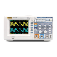
    What to do if my Rigol DS1204B Test Equipment oscilloscope doesn't display any waveform after pressing the RUN/STOP button?
    • A
      Ashley FriedmanAug 4, 2025
      If your Rigol Test Equipment oscilloscope isn't showing a waveform after you press RUN/STOP, here's what to check: * See if the Trigger Mode is set to “Normal” or “Single” and whether the trigger level is outside the signal range. If the trigger level is out of range, adjust it using the knob or by pressing the 50% button. * Alternatively, set the Trigger Mode to “AUTO”. * You can also push the AUTO button to attempt to automatically display the waveform.
  • M
    muellerlauraAug 8, 2025
    How to fix a dark screen on my Rigol Test Equipment oscilloscope after powering it on?
    • T
      Tim WellsAug 8, 2025
      If your Rigol Test Equipment oscilloscope screen remains dark after powering on, try these steps: * First, check the power cord connection to ensure it's secure. * Next, verify that the power switch is turned on. * If both are fine, restart the oscilloscope. If the problem persists after these steps, further assistance may be needed.
  • A
    Anthony FreemanAug 12, 2025
    Why doesn't a waveform appear on my Rigol DS1204B after signal acquisition?
    • H
      hooversarahAug 12, 2025
      If a waveform doesn't appear on your Rigol Test Equipment after signal acquisition, consider the following checks: * Ensure the probes are correctly connected to the signals and firmly attached to the channels. * Also, verify that the probes are properly connected to the object being tested and that the circuit generates a signal at the test point. * Finally, try repeating the acquisition.
  • J
    justincookAug 16, 2025
    How to get a stable waveform display on Rigol DS1204B Test Equipment oscilloscope?
    • R
      Rachel ReynoldsAug 16, 2025
      To achieve a stable waveform display on your Rigol Test Equipment oscilloscope, consider these adjustments: * Check that the Trigger Source is set to the channel you are using. * Verify the Trigger Type: use “Edge” for normal signals and “Video” for VIDEO signals. * Try switching the coupling to HF Rejection or LF Rejection to filter out noise that might be disturbing the trigger. * Adjust the trigger Sensitivity and the hold off time.
  • C
    Cassandra WilkinsAug 20, 2025
    What causes incorrect measurement results on Rigol DS1204B Test Equipment (10x higher or lower)?
    • A
      Adam FletcherAug 20, 2025
      If the measurement result on your Rigol Test Equipment is significantly off (10 times higher or lower than expected), the most likely cause is a mismatch between the probe attenuation and the channel attenuation. Check if the probe attenuation setting matches the channel attenuation setting.
  • H
    Holly PetersenAug 25, 2025
    How do I resolve a ladder-like waveform display on my Rigol DS1204B Test Equipment oscilloscope?
    • J
      juliesalazarAug 26, 2025
      If your Rigol Test Equipment oscilloscope displays a signal as a ladder-like waveform: * The time base setting may be too slow. Turn the horizontal knob to increase the horizontal resolution. * Alternatively, the display Type might be set to “Vectors”. Set it to “Dots” mode to improve the display.
  • S
    Sally KochAug 29, 2025
    Why can't my Rigol DS1204B Test Equipment connect to a PC or PictBridge printer via USB?
    • L
      Luis BrockAug 30, 2025
      If your Rigol Test Equipment is unable to connect to a PC or PictBridge printer via USB: * When connecting to a PC, if you see an “Unknown device” message or a prompt indicating a scanner or camera was found, go to the Utility menu, choose I/O Setting, and check the USB Device menu. If it's set to “PictBridge”, switch it to “Auto Detect” or “Computer”. * If connecting to a PictBridge printer is unsuccessful, switch the USB Device menu to “Auto Detect” or “PictBridge”. In either case, restarting the oscilloscope may be necessary.

Summary

Chapter 1 Quick Guide

General Inspect

Check for damage to the shipping container, instrument, and accessories upon receipt.

Panels and User Interface

Overview of the front and rear panels, buttons, knobs, and display layout.

Functional Check

Procedure to verify the instrument's basic operational status.

Probe Compensation

Adjusting probe characteristics to match channel input for accurate measurements.

Automatic Signal Display

Using the auto feature to automatically display input signals.

Vertical System Overview

Understanding controls for vertical position and Volts/div settings.

Horizontal System Overview

Controls for horizontal scale, position, and time base settings.

Trigger System Overview

Introduction to trigger modes, level, and settings.

Quick Function Overview

Using the Measure and Print functions for quick operations.

Chapter 2 Operating Your Oscilloscope

Vertical System Setup

Configuring analog channels (CH1-CH4) and MATH functions.

Horizontal System Setup

Setting Delayed Scan, TimeExpand, Time Base modes (Y-T, X-Y).

Trigger System Setup

Configuring trigger modes: Edge, Pulse, Video, Pattern, Alternative.

Sampling System Setup

Setting acquisition modes (Normal, Average, Peak Detect) and sampling.

Display System Setup

Adjusting display type, persistence, grids, and screen colors.

Store and Recall Functions

Saving and retrieving waveforms, setups, and bitmap files.

Utility Settings

Configuring I/O, sound, language, pass/fail, recorder, and calibration.

Automatic Measurements

Using automatic measurement functions for voltage and time parameters.

Cursor Measurements

Performing manual, track, and auto cursor measurements.

Run Control Buttons

Using Auto, Run/Stop, and Single buttons for waveform acquisition.

Chapter 3 Application Examples

Simple Signal Measurements

Displaying, measuring frequency, and peak-to-peak amplitude of a signal.

Signal Delay Observation

Viewing input/output signals and measuring circuit-induced signal delay.

Single-Shot Signal Capture

Capturing transient events using appropriate trigger setup.

Reducing Random Noise

Using acquisition settings and filters to minimize signal noise.

Cursor Measurement Examples

Measuring peak frequency and amplitude using cursors.

X-Y Operation for Phase

Using X-Y display to observe phase changes and differences.

Video Signal Triggering

Triggering on video fields or lines for stable display.

FFT Cursor Measurement

Measuring amplitude and frequency in FFT mode using cursors.

Pass;Fail Test Example

Performing pass/fail tests by comparing input signals to a mask.

Chapter 4 Troubleshooting

Power On and Display Issues

Resolving issues like a dark screen or no display after powering on.

Waveform Acquisition Problems

Troubleshooting when waveforms do not appear after signal acquisition.

Measurement Accuracy Issues

Addressing discrepancies in measurement results compared to expectations.

Stable Waveform Display

Steps to ensure a stable waveform display.

No Waveform After Run;Stop

Resolving issues where no waveform appears after using Run/Stop.

Waveform Display Format Issues

Troubleshooting ladder-like waveform display or slow refresh.

USB Connectivity Problems

Resolving issues connecting to PCs or printers via USB.

Chapter 5 Specifications

Technical Specifications

Detailed specifications for acquisition, inputs, horizontal, vertical, and trigger.

General Specifications

Overview of display, power, environmental, mechanical, and calibration details.

Chapter 6 Appendixes

DS1000 B Series Accessories

List of standard and optional accessories included with the oscilloscope.

Warranty Information

Details on product warranty, coverage, and service.

Care and Cleaning Guidelines

Instructions for proper care, cleaning, and handling of the instrument.

Rigol DS1204B Specifications

General IconGeneral
Bandwidth200 MHz
Channels4
Display7 inch TFT LCD
Timebase Range2 ns/div to 50 s/div
Trigger ModesEdge, Pulse, Video, Slope, Alternate
Weight2.5 kg
Vertical Resolution8 bits
Input CouplingAC, DC, GND
Sample Rate2 GSa/s
Display Resolution800 x 480
Trigger TypesEdge, Pulse, Video
InterfacesUSB, LAN, GPIB (optional)
Input Impedance1 MΩ
Power Supply100-240 VAC, 45-440 Hz

Related product manuals