Do you have a question about the Rigol DS1102/4B and is the answer not in the manual?
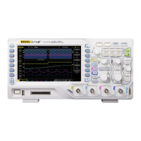
Introduces the oscilloscope's front panel layout, knobs, and buttons for operation.
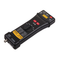
Explains how to adjust probe characteristics to match the oscilloscope channel input for accurate measurements.
Covers the setup and adjustment of trigger controls to stabilize waveform display.
Covers channel coupling, bandwidth limit, probe attenuation, digital filters, and vertical controls.
Explains controlling time base, position, and display modes like Y-T, X-Y, and Roll.
Details trigger modes, sources, slope, sweep, and advanced trigger settings for stable signal capture.
Details how to perform automatic voltage and time measurements on signals.
Explains using manual, track, and auto cursor modes for signal analysis and measurement.
Explains setting up pass/fail tests by comparing signals against predefined masks.
Provides solutions for common problems like dark screens, no waveforms, or unstable displays.
Details sampling modes, rates, averages, input coupling, impedance, and probe attenuation factors.
Outlines bandwidth, sensitivity, gain accuracy, and measurement accuracy for the vertical system.
| Bandwidth | 100 MHz |
|---|---|
| Vertical Sensitivity | 2 mV/div to 10 V/div |
| Trigger Modes | Edge, Pulse, Video, Slope, Alternate |
| Timebase Range | 5 ns/div to 50 s/div |
| Display Resolution | 800 x 480 |
| Vertical Resolution | 8 bits |
| Input Coupling | DC, AC, GND |
| Sample Rate | 1 GSa/s |
| Display | 7 inch TFT LCD |
| Input Impedance | 1 MΩ ± 2% |
| Interfaces | USB |
| Power Supply | 100-240 VAC, 50/60 Hz |