Rinnai Australia 24 Installation Manual
GENERAL INSTALLATION INSTRUCTIONS
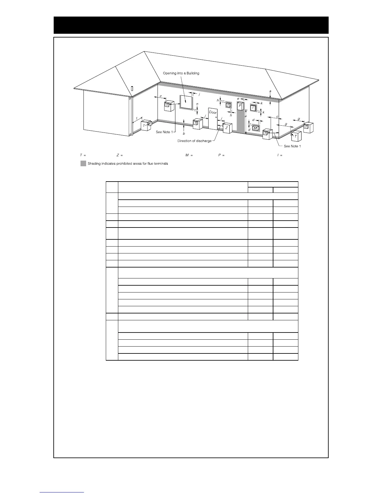
HORIZONTAL FLUE TERMINAL CLEARANCES
Extract from AS/NZS 5601
Flue terminal Fan assisted flue appliance only Gas meter Electricity meter or fuse box Mechanical air inlet
Natural draft Fan assisted
• Appliances up to 50 MJ/h input 300 200
• Appliances over 50 MJ/h input 500 300
b From the ground, above a balcony or other surface * 300 300
c Front a return wall or external corner * 500 300
d
From a gas meter (M) (see 5.11.5.9 for vent terminal location of regulator )
(see Table 6.6 for New Zealand requirements) 1000 1000
e From an electricity meter or fuse box (P) † 500 500
f From a drain pipe or soil pipe 150 75
g Horizontally from any building structure* = or obstruction facing a terminal 500 500
h From any other flue terminal , cowl, or combustion air intake † 500 300
• Appliances up to 150 MJ/h input * 500 300
• Appliances over 150 MJ/h input up to 200 MJ/h input * 1500 300
• Appliances over 200 MJ/h input up to 250 MJ/h input * 1500 500
• Appliances over 250 MJ/h input * 1500 1500
• All fan-assisted flue appliances , in the direction of discharge - 1500
k From a mechanical air inlet, including a spa blower 1500 1000
• Space heaters up to 50 MJ/hr input 150 150
• Other appliances up to 50 MJ/hr input 500 500
• Appliances over 50 MJ/h input and up to 150 MJ/h input 1000 1000
• Appliances over 150 MJ/h input 1500 1500
1
Where dimensions c, j or k cannot be achieved an equivalent horizontal distance
measured diagonally from the nearest discharge point of the terminal to the opening
may be deemed by the Technical Regulator to comply.
2
See Clause 6.9.4 for restrictions on a flue terminal under a covered area.
3
See Figure J3 for clearances required from a flue terminal to an LP Gas cylinder.
A flue terminal is considered to be a source of ignition.
4
Ref. Item
a
Min. clearances (mm)
Below eaves, balconies and other projections:
j
Horizontally from an openable window, door, non-mechanical air inlet, or any other opening into a building
with the exception of sub-floor ventilation:
Vertically below an openable window, non-mechanical air inlet, or any other opening into a building with the
exception of sub-floor ventilation:
NOTES:
† - Prohibited area below electricity meter or fuse box extends to ground level.
FIGURE 6.2 (in-part) MINIMUM CLEARANCES REQUIRED FOR BALANCED FLUE TERMINALS, FAN-ASSISTED FLUE
TERMINALS, ROOM-SEALED APPLIANCE TERMINALS AND OPENINGS OF OUTDOOR APPLIANCES
* - unless appliance is certified for closer installation
For appliance s not addressed above acceptance should be obtained from the Technical Regulator.
n
 Loading...