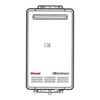
REU-2532FFU Series 48 Rinnai
Nature of Fault
Examination Point
Diagnostic Point
Values
Y/N
Action
Repair
N
o
Yes Go to A – (7) 2. Measure the
voltage at connector
F with appliance
power supply on.
F – Black ~ white
100 ~ 120 VAC
F
7
– Blue ~ Brown
100 ~ 120 VAC
Are valves within
those specified at left.
No Replace
transformer
8
Yes Check cable for
shorts or broken
wires. Replace
remote control
9
7. Check remote(s)
(where connected).
Measure voltage
between remote
control terminals at
D.
11 ~ 13 VDC Digital
No Replace PCB. 10
Yes Go to B–1-2 1. Measure voltage
between red ~ black
of connector B
4
.
11 ~ 13 VDC
No Replace PCB 11
Yes Go to B - 2
B. Digital monitor
lights up, but
combustion does
not commence.
(When remotes
are connected).
1. Check water flow
sensor.
2. Measure voltage
between yellow ~
black at connector B
4.
4 ~ 7 VDC
No Replace water
flow sensor.
12
Yes Replace PCB 13 Error code “72”
displayed on the
digital monitor.
2. Check flame rod # Measure resistance
between flame rod
terminal C
1
and earth
Resistance > 1MΩ?
No Replace flame
rod
14
Yes Replace water
temperature
thermistor.
15 Error code “32”
displayed on
digital monitor.
3. Check outgoing
water temperature
thermistor.
# Disconnect
connector B
5
and
measure resistance.
Open circuit: > 1MΩ
Short circuit: <1Ω
Are values as shown
at left.
No Go to B-4
Yes Go to B–5-2 1. Check motor.
Measure voltage
between black ~ red
at connector A
1
.
6 ~ 45 VDC (Fan on)
0 VDC (Fan off)
No Replace PCB 16
Yes Go to B-4-3 2. Check fan rotation
sensor. Measure
voltage between
black ~ yellow at
connector A
1..
11 ~ 13 VDC
No Replace PCB 18
Yes Go to B-5
Error code “61”
displayed on
digital monitor
4. Check combustion
fan.
3. Measure voltage
between black ~
white of connector
A
1.
6 ~ 45 VDC
No Replace fan 19
 Loading...