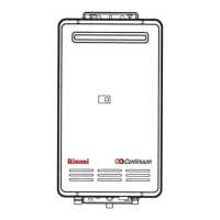
REU-2532FFU Series 53 Rinnai
Dip switches #7 and #8 (combustion control switches), MUST be returned to the “Off” position, after
setting the pressures. Dip switch #1 MUST be returned to the proper position based upon the length
of the Vent/Air Intake pipe. (“ON” position = Short Vent/Air Intake – 6’ to 21’ equivalent length,
“OFF” position = Long Vent/Air Intake – 22’ to 41’ equivalent length).
1. Turn off the gas to the water heater. Remove the manometer connection. Reinstall the pressure port plug.
Turn on the gas to the water heater and check for gas leaks around test port with a leak solution.
2. Reinstall the front cover and place the unit back into operation.
3. Verify you are getting the proper water temperature, as set on the controller at your outlets. If controllers are
not being used the output temperature should be 120°F.
Figure #1 Figure #2
High pressure setting “Pot”
Dip switches #7 and #8 are used when
adjusting low and high fire manifold
gas pressures, as stated in the gas
ressure settin
rocedure.
Manifold gas
pressure test
port.
Regulator adjustment screw used when
setting low and high fire manifold gas
pressures only. DO NOT, adjust this
screw without following gas pressure
setting procedures.
 Loading...