Do you have a question about the Rinnai REU-24 W-A and is the answer not in the manual?
| Brand | Rinnai |
|---|---|
| Model | REU-24 W-A |
| Category | Water Heater |
| Language | English |
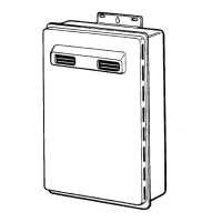
Describes the noise reduction design of the unit.
Highlights ease of use and temperature control features.
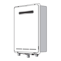
Details the unit's compact and lightweight design for easier installation.
Mentions automatic safety devices and frost protection.
Explains energy-saving features like direct ignition and efficient combustion.
Monitors combustion, isolates gas if flame is absent.
Shuts off gas if flame persists after tap closure.
Prevents overheating by shutting off solenoids.
Isolates gas if incoming water flow stops.
Shuts down unit if heat exchanger overheats.
Releases excess pressure from the heat exchanger.
Monitors fan speed for optimal combustion.
Prevents freezing of water in the appliance.
Mixes hot water with cold water for temperature control.
Monitors combustion and adjusts air/gas ratio.
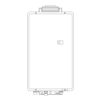
Visual representation of the appliance's internal components and connections.
Data used for calculating required parameters for temperature control.
Information from outgoing water temp thermistor for control adjustments.
Formula and example for calculating water flow rate.
Formula for calculating gas input based on temperature and flow.
Procedure for handling faulty remote controls.
Setting default temperature when remote controls are not used.
Regulates incoming water pressure.
Detects water flow using a turbine/magnetic pulse device.
Controls water flow via mechanical diaphragm and valve system.
Supplies air for combustion, speed controlled for optimal mixture.
Mixes hot water with cold water for temperature adjustment.
Pre-mix gas and air combustion system.
Controls gas flow based on temperature and flow.
Increases flexibility of gas modulation by supplying gas to manifolds.
General overview of common problems and their solutions.
Explains error codes displayed on the digital monitor.
Detailed troubleshooting flowcharts for various fault conditions.
Troubleshooting steps for low preset temp and very hot water.
Troubleshooting steps for high remote setting and cold water.
Steps to diagnose and fix non-operating anti-frost heaters.
Steps to diagnose and fix anti-frost heaters that remain on.
Analysis of the PCB power supply transformer.
Analysis of safety circuit components like fusible link.
Analysis of the water flow sensor and its output.
Analysis of the combustion fan motor specifications and connections.
Analysis of the sparker and its voltage output.
Analysis of solenoid valves, including voltage and resistance.
Analysis of the modulating valve's current and resistance.
Analysis of flame rod current and insulation resistance.
Analysis of anti-frost heater resistances.
Analysis of the frost sensor switch resistance.
Analysis of EWFC device and bypass motor.
Analysis of thermistor resistances at various temperatures.
Steps to remove the appliance's front cover.
Steps for removing the Printed Circuit Board unit.
Steps for removing the gas solenoid valve assembly.
Steps to remove the electronic water flow control device.
Steps to remove the burner assembly.
Steps to remove the combustion chamber.
Steps to remove thermistors (incoming, outgoing, outlet).
Details the methodology and conditions of showering temperature tests.
Summarizes the key findings from the showering temperature tests.
Discusses practical applications of test findings for appliance design.
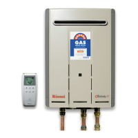
Instructions for powering on the Infinity 24 water heater.
Guide on how to increase or decrease the water temperature setting.
How to switch temperature control between master and sub units.
Instructions for powering off the Infinity 24 water heater.