EasyManua.ls Logo

Rinnai RHFE-556FTD - User Manual

Rinnai RHFE-556FTD
26 pages
Print Icon
To Next Page IconTo Next Page
Loading...
How to use your
Space Heater
. Energysaver RHFE-SGFDT
Rinnai
Guarantee
Layout of appliance
Features
Safety Points
Operation
Adjusting Temperature
Humidifier
Installer
<
<
<
<
<
<
.
<
<
I
SERVICE CoNi’ACrs
NZ (09) 625 4285
0800 RINNAI
Question and Answer IconNeed help?

Do you have a question about the Rinnai RHFE-556FTD and is the answer not in the manual?

Summary

Rinnai Service Contacts

Energysaver Fixed Time Operation

Rinnai Appliance Guarantee

Heater Components Overview

Control Panel Layout and Indicators

Heater Features Explained

Filter Indicator Function

Indicates when the fan filter is blocked and requires cleaning. Located on the appliance.

Vertical Louvre Airflow Adjustment

Allows adjustment of airflow direction by bending louvres left or right using a tool.

Humidifier Tray Operation

Integral tray to raise humidity level in the room. Filled with water.

Fixed Time Operation Feature Details

Automatically stops appliance after a fixed time period (1-12 hours) for energy saving.

Memory Function for Preset Temperatures

Micro-computer records preset temperatures for comfort level maintenance.

General Safety Precautions

Heater Operation Guide

Opening the Control Panel

Instructions on how to open the control panel cover using a finger.

Turning the Heater On Procedure

Steps to turn on the heater, indicators, and initial ignition process.

Turning the Heater Off Procedure

Procedure for switching off the heater and the convection fan's cooling process.

Room Temperature Setting

Fan Filter Cleaning and Maintenance

Humidifier Tray Filling Instructions

Vertical Louvre Adjustment Guide

Routine Heater Care and Maintenance

Troubleshooting: Pre-Service Checks

Pre-Service Checks: Ignition Issues

Checks to perform when the heater does not operate or fails to ignite.

Pre-Service Checks: Combustion Issues

Checks for issues like clunking noise, unit not heating, or blocked louvres.

Pre-Service Checks: Post-Operation

Checks related to the convection fan continuing to run after the unit is turned off.

Pre-Service Checks: General Issues

Checks for issues like steam discharge or unit cutting off without reason.

Heater Error Message Codes

Installation Part Checklist

Heater Location: General Guidelines

Location: Flueing Requirements

Guidance on flue placement and clearances, avoiding flammable materials.

Location: Airflow and Clearances

Ensuring combustible materials do not contact the heater and managing curtain proximity.

Heater Location: Flue and Terminal Setup

Location: Flue Type and Placement

Specifies Rinnai flue kits, external flue terminals, and placement near opening windows.

Location: Flue Size Options

Lists available flue lengths (AA, A, B, C, D, E) and coaxial flue options.

Location: Snow Area Considerations

Advice for snow areas to keep flue terminals clear of snow.

Location: Flue Manifold Installation Clearances

Diagrams showing minimum clearances and distances for flue manifold installation.

Location: Side Clearance Requirements

Details required side clearances from flammable and non-flammable walls.

Location: Fitting Back Covers

Instructions on fitting back covers (sides only) using screws and lugs.

Location: Gas Connection Fitting

Guidance on fitting a suitable copper flare elbow to the appliance inlet.

Heater Location: Mounting and Environment

Location: Dusty Environment Avoidance

Advises against installing the heater in unusually dusty areas.

Location: Weatherboard Wall Drilling

Instructions for drilling through weatherboard walls for flue installation.

Location: Flue Guard Safety

Recommends using a flue guard if the terminal is accessible to children.

Location: Floor Leveling Requirement

Requirement for the floor to be level for proper installation.

Location: Electrical Cord Safety

Prohibits using electrical extension cords and specifies keeping the power cord away from the flue.

Location: Flue Manifold Positioning

Guidance on positioning the flue manifold within a shaded area to avoid studs.

Location: Wall Mounting Bracket Installation

Detailed steps for positioning and attaching wall mounting brackets for the heater.

Sleeve and Manifold: Standard Wall Installation

Sleeve;Manifold: Disassembly Steps

Procedure to disassemble the manifold from the sleeve and its components.

Sleeve;Manifold: Sleeve Length Adjustment

Measuring wall thickness and adjusting sleeve length to protrude 5-10mm from the wall.

Sleeve;Manifold: A;AA Flue Extension Removal

Instructions for removing extension piece 'C' for specific flue types.

Sleeve;Manifold: Fixing Sleeve to Wall

Securing the sleeve to the wall using provided screws, ensuring correct orientation.

Sleeve and Manifold: Standard Wall Installation (Cont.)

Sleeve;Manifold: Terminal Seal Verification

Verifying the rubber seal is correctly placed on the terminal, with an option for weatherboard walls.

Sleeve;Manifold: Terminal Installation Procedure

Inserting the terminal into the sleeve, aligning marks and fixing ties.

Sleeve;Manifold: Securing Ties

Pulling and clipping ties over lugs inside the sleeve, cutting excess, and bending them.

Sleeve;Manifold: Inner Connection Assembly Installation

Pushing the inner connection assembly into the terminal tube and securing with screws.

Sleeve;Manifold: Manifold Orientation Flexibility

Note that the manifold can be turned after attachment.

Fitting Unit Components: Air Inlet and Flue Connections

Fitting Unit: Air Inlet Hose Connection

Steps for connecting the air inlet hose, including detail of hose clip.

Fitting Unit: Clamps and Insulation Sleeve

Fitting locking clamp, screw clamp, and insulation sleeve to the flue/manifold.

Fitting Unit: Connecting Flue to Manifold

Connecting the flue outlet to the manifold by extending the sliding tube fully.

Fitting Unit: Locking Clamp Installation

Fitting the locking clamp over the connection between the sliding tube and manifold.

Fitting Unit: Screw Clamp Installation

Securing the sliding tube and flue elbow using the screw clamp.

Fitting Unit: Insulation Sleeve Attachment

Sliding the insulation sleeve up to the flue manifold and securing it with a clip.

Gas Pressure Testing and Adjustment

Testing: Pressure Checking Procedure

Detailed steps for checking gas pressure at low and high settings using a gauge.

Testing: Pressure Re-setting Guide

Step-by-step guide to re-setting low and high gas pressures using control panel buttons.

Fitting Heater: Top Spacer and Wall Clip

Fitting: Securing Heater to Wall

Clipping top spacer into wall brackets and securing with screws to fix heater to wall.

Fitting: Unit Levelling

Using adjustable legs to level the unit if necessary.

Fitting: Customer Operation Briefing

Explaining heater operation to the customer once it's confirmed to be working correctly.

Fitting: Post-Installation Fault Procedure

Procedure to follow if the heater cannot be operated correctly after installation.

Heater Wiring Diagram

Heater Block Diagram and Dimensions

Rinnai New Zealand Ltd. Contact

Overview

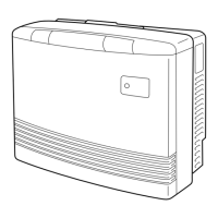
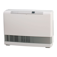
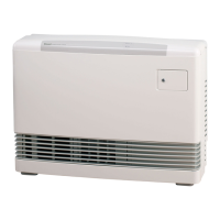
The Rinnai Energysaver RHFE-556FDT is a space heater designed for efficient and safe heating. It operates using a forced flue system and is controlled by a micro-computer, incorporating several safety devices to ensure continuous and reliable operation.

Function Description:

The primary function of the RHFE-556FDT is to provide warm air heating for indoor spaces. It features a warm air discharge duct with adjustable louvres to direct airflow. An integral humidifier tray allows for increased humidity levels in the room when filled with water, which can enhance comfort and potentially allow the heater to run at a lower temperature while maintaining the same comfort level. The appliance also includes a fixed time operation feature, allowing users to set it to automatically stop after a chosen period (1, 2, 3, 6, 8, 10, or 12 hours), which can lead to energy savings by preventing the heater from running unnecessarily. A memory function records the selected pre-set temperature to maintain preferred comfort levels.

Important Technical Specifications:

  • Input: 23 MJ/h
  • Ignition: Continuous Spark
  • Burner: Stainless Bunsen Type
  • Gas Inlet: R1/2 15 BSP Connection
  • Flue: Forced Flue (components supplied with appliance)
  • Gas Control: Rinnai Electronic Modulating Controls
  • Electrical Supply: 230V, 50 Hz. It is fitted with a supply lead and a 3-pin plug. The replacement part number for the plug is Rinnai part number 3010.
  • AGA Approval No: 5209

Usage Features:

The heater features a concealed control panel with an ON/OFF switch, room and pre-set temperature selection buttons. An indicator display shows power ON/combustion status, filter status, and temperature/error codes. The selected room temperature is displayed, with a flashing LED indicating the current room temperature and a steady LED indicating the selected temperature. Temperature can be set to "L" (low, about 10°C), "H" (continuously high), or in 2°C steps from 16°C to 26°C. The ON indicator changes from red to green when the heater reaches the pre-set temperature and stops running, operating at eight-minute intervals to maintain warmth.

The vertical louvres can be adjusted using a screwdriver or similar tool to alter the direction of airflow, though they are not designed for more than 6 adjustments. The humidifier tray, built into the warm air discharge duct, can be filled by pulling off the bottom trim panel and sliding the tray forward. It should be filled about once a day during the heating season, but not while the heater is running.

Maintenance Features:

The RHFE-556FDT requires minimal maintenance. The rear fan filter should be cleaned once a week during the heating season to protect the room air fan from dust and lint and prevent unnecessary strain on the appliance. When the filter becomes covered with dust and the internal temperature rises, a filter indicator will flash, prompting cleaning. If the filter indicator continues to flash due to lack of cleaning, the appliance will stop, and "20" will flash on the digital display, indicating that a safety device has functioned. The filter must be cleaned before operating the heater again. The outer case and louvre section should be wiped with a damp cloth; solvents should not be used as they may melt or distort plastic parts.

The appliance is equipped with several safety devices, including an Ignition Safety Device, Burner Safety Device, Overheat Safety Device, Power Failure Safety Device, Power Surge Safety Device, and Fan Delay Safety Device. In case of a fault, an error message will flash on the control panel display, assisting in diagnosis and potential user resolution. Common remedies for issues like "Not Plugged In" (plug in), "Power Cut" (re-ignite manually), "Air in gas pipe" (purge air by installer), "Gas Filter Blocked" (service call), "Miss Ignition" (service call), "Flue terminal obstructed" (clear obstruction), "Louvre obstructed" (clear obstruction), "Air filter blocked" (clean filter weekly), "Gas Escape" (service call), and "Gas turned off at meter" (turn gas on) are provided. For persistent error messages, users are advised to contact Rinnai or a service agent.

Rinnai RHFE-556FTD Specifications

General IconGeneral
BrandRinnai
ModelRHFE-556FTD
CategoryHeater
LanguageEnglish

Related product manuals