E
Eric MoralesJul 25, 2025
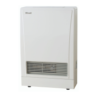
How to fix Rinnai Heater with no operation lamp?
- SSavannah GrayJul 25, 2025
If the operation lamp on your Rinnai Heater is not lit, plug in the power cord and press the control panel ON / OFF button.
How to fix Rinnai Heater with no operation lamp?
If the operation lamp on your Rinnai Heater is not lit, plug in the power cord and press the control panel ON / OFF button.
Rinnai Energysaver Range is certified by the Australian Gas Association.
Lists all items included in the Rinnai Energysaver Space Heater package.
Fields for installer's name, company, address, contact details, and credentials.
Fields for model number, serial number, and installation address.
Critical safety warnings about installation, use, and compliance.
Minimum clearances for installation and effects of heat radiation on materials.
Overview of safety devices like overheat, flame failure, fuses, and fan control.
Safety functions related to power failure and electrical fuses.
Rinnai service network availability and recommended service interval of 2 years.
Features like room sealing, ignition, memory, humidifier tray, and filter indication.
Features for child lock, timers, economy mode, override, and remote control.
Details on 7-step automatic heat control and pre-heat functions.
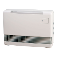
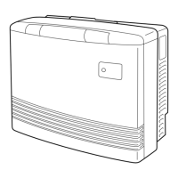
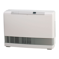
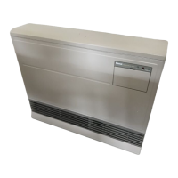
Diagrams identifying key components of different Energysaver models.
Diagram and labels for the control panel of specific models.
Explains the function of each numbered button on the control panel.
Diagram and labels for the control panel of the RHFE-1004FTR model.
Explains the function of each numbered button on the control panel.
Diagram and controls for the RHFE-556FDT model.
Diagram and controls for the RHFE-1004FDT model.
Instructions on how to use the remote control for manual operation.
Explanation of remote buttons, battery type, and replacement.
Step-by-step guide for switching the heater on and off.
How to display and adjust the desired room temperature settings.
How to use Economy mode and activate/deactivate Child Lock.
Details on override function and specific operation for FDT models.
Steps to turn off the heater and adjust temperature settings.
Step-by-step guide to setting the current time on the appliance.
Instructions for programming timer start and end times for heating.
Steps to select timers for heating, including pre-heat and set-and-forget.
Information on pre-heat, humidifier tray use, and vertical louvre adjustment.
Notes on steam discharge from the flue terminal during operation.
Instructions for general cleaning and fan filter maintenance.
A checklist of common issues and their corresponding remedies.
Detailed explanations for various operational symptoms that may occur.
Guide to error codes, probable causes, and recommended comments for diagnosis.
Key specifications including physical size, gas, and electrical requirements.
Information on flue type, connection, and available flue systems.
Diagrams and measurements for specific models' physical size and clearances.
Diagrams and measurements for the RHFE-557FTR model's physical size.
Diagrams and measurements for RHFE-1004FTR/FDT models' physical size.
Guidance on positioning, flueing, and gas supply requirements.
Requirements for the power cord, plug, and dedicated power point.
Diagrams showing direct, extended, sideways, external, and in-wall flue setups.
Minimum clearance requirements for flue terminals as per AS/NZS 5601.
Tables and diagrams showing wall penetration dimensions for different heater models.
Diagrams illustrating direct, extended, under floor, and in-wall flue setups.
Steps for unpacking, checking for damage, and gas type verification.
Procedures for connecting the appliance to the gas supply and mounting brackets.
Steps for connecting flue, gas supply, and securing panels.
Instructions for leak testing, fitting covers, and replacing the fan filter.
Detailed steps for checking and adjusting gas pressure settings.
Instructions for fitting spacers and securing the heater assembly.
Guidance on what to do if the heater fails to operate correctly.
Electrical schematic for the RHFE-557FTR model.
Key for understanding the wiring diagram symbols and component labels.
Continuation of the electrical schematic and component list for RHFE-557FTR.
Electrical schematic for the RHFE-556FTR model.
Continuation of the electrical schematic and component list for RHFE-556FTR.
Electrical schematic for the RHFE-1004FTR model.
Continuation of the electrical schematic and component list for RHFE-1004FTR.
Electrical schematic for the RHFE-1004FDT model.
Continuation of the electrical schematic and component list for RHFE-1004FDT.
Checklist for installers to ensure proper installation and customer instruction.