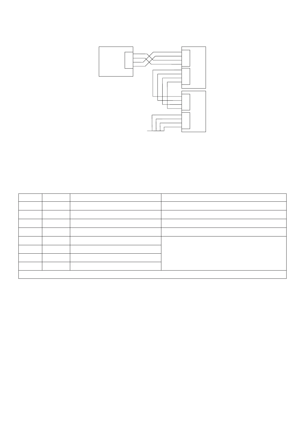
2.8.4 RS485/RS422 Bus Connection
Pins 6 to 9 of serial 1 are connected directly to pins 6 to 9 of the Serial 2 connector. This provides for convenient
implementation of multi-drop RS422 or RS485 communications.
SERIAL
1
SERIAL
2
UNIT 1
UNIT 2
2.9 DB9 Serial Port 2 Connection (C520 Only)
2.9.1 Overview
This port is generally used to drive serial printers (with DTR handshaking) and remote displays. It can also
be used as a network port. All connections for the port are on the Serial 2 connector. This is a standard DB9
socket requiring a female DB9 plug. The only output available from Serial 2 is RS232. The connections for
this are shown below.
Pin No Function Description Connect to external device
2 RX2 RS232 receive Transmit (DB9 pin 3)
3 TX2 RS232 transmit Receive (DB9 pin 3)
4 DTR RS232 DTR handshake DTR (DB9 pin 4)
5 GND2 RS232 ground Ground (DB9 pin 5)
6 RA Serial 1 RS422/RS485 receive A-
If RS232 is used, do not connect pins 6..9. A
null-modem cable is not suitable. These pins
are connected internally to serial port 1.
7 RB Serial 1 RS422/RS485 receive B+
8 TA Serial 1 RS422/RS485 transmit A-
9 TB Serial 1 RS422/RS485 transmit B-
Shield: Connect as directly as possible to the metal DB9 shell.
2.10 Optional Module Connections
Two optional modules can be connected. These provide a range of external drivers and features. See Section 15
and the module datasheets (for module specific connection details).
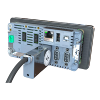
2.11 Ethernet Connection
A standard 10/100 Ethernet port is provided. See Section 14.
2.12 USB Host and Device Connections
A USB host and USB device interface are provided. See Section 10.
9 C500-600-2.0.3
 Loading...