Do you have a question about the Riso RN SERIES and is the answer not in the manual?
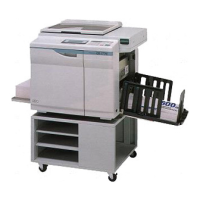
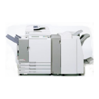
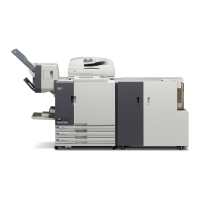
Introduction to the technical service information for the RISOGRAPH RN series.
Guidelines for safe and effective work procedures, including inspection, removal, and assembly.
Step-by-step instructions for removing various exterior covers of the machine.
Details on removing the controller unit and the system PCB for maintenance or replacement.
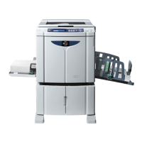
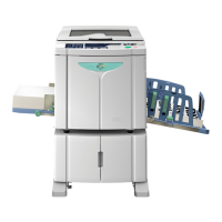
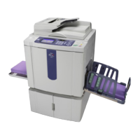
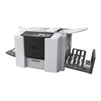
Technical specifications for the metric model of the RN series duplicator.
Technical specifications for the inch model of the RN series duplicator.
Explanation of the main drive section's operational mechanism, including motor and pulleys.
Procedures for removing and reassembling the main drive unit components.
Instructions for adjusting the print drum position-A for optimal performance.
Overview of the paper feed tray mechanism and its paper size detection.
Steps for removing and reassembling components of the first paper feed system.
Procedures for adjusting the upper limit sensor position in the paper feed system.
Explanation of the second paper feed mechanism, including cam and roller operations.
Instructions for removing and reassembling parts of the second paper feed system.
Procedure for adjusting the timing cam mounting position for correct paper feeding.
Description of the press section mechanism, including pressure roller and solenoid operations.
Steps for removing and reassembling the pressure roller and related components.
Procedure for adjusting the mounting position of the pressure lever assembly.
Overview of the paper ejection mechanism, including transfer belts and sensors.
Instructions for removing and reassembling components of the paper ejection system.
Procedure for adjusting the separator mounting position to prevent paper jams.
Explanation of print drum mechanisms, including master detection and set detection.
Detailed steps for removing and reassembling print drum components.
Procedures for adjusting squeegee gap and pressure balance for optimal print quality.
Explanation of the clamp unit home positioning and master release mechanisms.
Instructions for removing and reassembling the clamp unit and its motor/sensors.
Description of the master removal mechanism, including sensor and compression.
Procedures for removing and reassembling master removal system components.
Explanation of scanner table setting and original scanning mechanisms.
Instructions for removing and reassembling scanner unit components and stage glass.
Procedures for adjusting scanner motor speed and scan positions for image quality.
Overview of ADF original set and scanning mechanisms, including sensors and motors.
Steps for removing and reassembling ADF unit components like rollers and sensors.
Procedures for adjusting ADF scan start position and image skew for optimal scanning.
Explanation of master making and loading mechanisms, including thermal print head.
Instructions for removing and reassembling master making components like rollers and cutter.
Procedures for adjusting thermal print head power and master feeding parameters.
Timing charts for various initialization operations of machine components.
Timing charts illustrating the sequence of operations during printing.
Timing charts detailing elevator motor operation for raising and lowering.
Timing charts for print drum peripheral operations like clamping and inking.
Timing charts for print speed, intensity, and position adjustments.
Timing charts for the master removal process, including vertical transport and compression.
Timing charts for the master making process, from scanning to final creation.
Overview of error code structure, error types, and error point classifications.
A comprehensive list of all panel messages categorized by error type.
Detailed explanations of panel messages, including error conditions and reset methods.
List of errors that are retained even after the power is switched off.
Instructions for starting, operating, and ending test mode procedures.
Guide to checking the status of various sensors and switches using test mode.
Procedures for checking the operation of motors and solenoids via test mode.
Performing operational checks on various machine units using test mode.
Displaying current machine settings and data without allowing changes.
Instructions for setting and adjusting various machine parameters via test mode.
Guide to customizing initial settings for image processing, print speed, and other parameters.
Procedure for replacing the ROM chip on the main PCB.
Instructions for replacing the battery on the main PCB.
Steps for replacing the main PCB, including data backup and test mode operations.
Procedure for replacing the ink cartridge set switch PCB.
Guide to adjusting master creation, scanning, and print positions.
Important notes regarding the assembly and handling of the stay assembly.
Block diagram illustrating the interconnections between various areas and PCBs.
Diagrams showing the physical location of PCBs within the machine.
Table detailing the function and model compatibility of each PCB.