Do you have a question about the Riso GR 3770 and is the answer not in the manual?
Introduces the manual, RISO Group contacts, and technical hotline.
Provides critical safety instructions for handling lithium batteries.
Details important safety precautions for electrical connections and components.
Outlines installation procedures and warnings for initial setup.
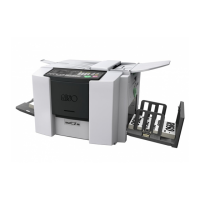
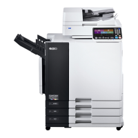
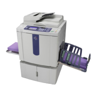
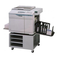
Highlights key technical advancements and new features of the GR3770 model.
Lists comprehensive technical specifications for the GR3770 duplicator.
Details accessory and consumable compatibility for the GR3770.
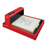
Explains operational principles of drum insertion, ink detection, and ink supply.
Provides procedures for removing and disassembling drum-related components.
Explains operational principles of the flat bed scanner system and its components.
Details procedures for removing various components of the flat bed scanner.
Provides procedures for removing the thermal print head and related parts.
Details procedures for adjusting thermal power of the print head.
Explains operational principles of the clamp unit and master loading systems.
Provides procedures for removing clamp and loading unit components.
Guides on how to enter, operate, and exit test modes.
Lists current states of sensors and switches with buzzer indications.
Details tests for motors and solenoids using START key.
Details memory switch settings for various machine adjustments.
Procedures for clearing memory and stopping counters.
Tests for sequential operation of various machine functions.
Tests for panel display, LEDs, and key input.
Lists and explains trouble messages displayed on the T display.
Lists and explains additional trouble messages.
Displays and explains confirmation messages for settings.
Messages related to replacing consumables like ink cartridges.
Diagram showing the interconnections between main PCBs.
Illustrates the physical placement of PCBs within the machine.
Details and pinouts for the System PCB2.
Details and pinouts for the Image Processing PCB (IPIF).
Details and pinouts for the Motor Control PCB MK2.
Details and pinouts for the Drum Control PCB3.
Details and pinouts for the ADF PCB.
Details and pinouts for the FBI PCB.
Details and pinouts for the Option PCB AIII.
Details and pinouts for the LCD Control PCB.
Details and pinouts for the 100-120V Power Supply PCB.
Details and pinouts for the 200-240V Power Supply PCB.
Details and pinouts for the TPH Sub PCB.