DESCRIPTION OF PCBs
SYSTEM PCB2
GR3770APX(II)-3
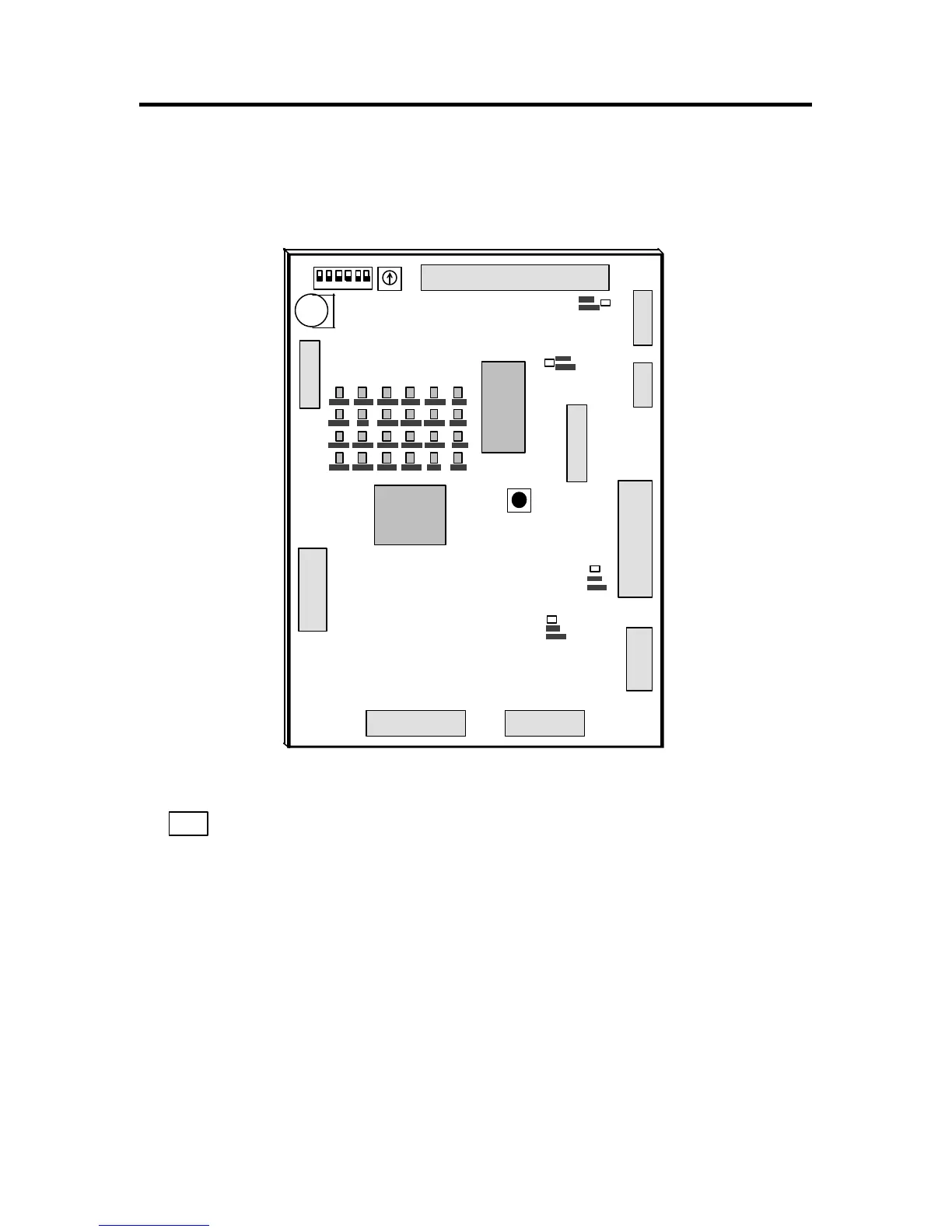
3. SYSTEM PCB2
CN15
1
2
CN2
To LCD Control
PCB CN2
29
30
To Drum Control
PCB2 CN1/CN2
1
CN5
To Components
CN7
10
To Power Supply PCB
CN5/CN2
CN6
B2
B1
A2
A1
B30
B29
A30
A29
CN14
To Option PCB
CN1
22
21
To Components
2
1
CN9
2
1
49
50
To Components
To Image Processing
PCB CN2
To Job Separator
To Motor Control
PCB MK2 CN2
CN4
CN10
8 1
1
15
2
1
40
39
CN3
SW2
1 2 3 4 5 6
SW3
CR
2450
U21
SW1 FREE
SW
SW1 : Drum(Main motor) 30 rpm
SW2 : Machine Selection HEX SW
HEX SW set to 3 GR377(Japanese version)
HEX SW set to 7 GR3770(US version/ Ledger)
HEX SW set to A GR3770(EU,ASIA/ A3)
HEX SW set to D GR3770(LATIN/ A3)
SW3 : Machine Selection DIP SW
Set all DIP SW(1 through 6) to “OFF” position