4 Assembly and connection
RITTAL cooling unit assembly and operating instructions 11
EN
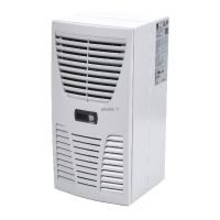
4.3.4 Full internal mounting of the cooling unit
• Carefully remove the louvred grille and the infill
panel from the enclosure by pulling forwards.
• Carefully disconnect the connector from the rear of
the display.
Fig. 15: Remove the louvred grille and disconnect
the display
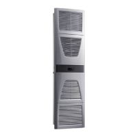
• Cut the supplied sealing tape to the correct length
and stick it carefully along the front enclosure half
so that no gaps are left at the connection points.
Fig. 16: Attach the sealing tape
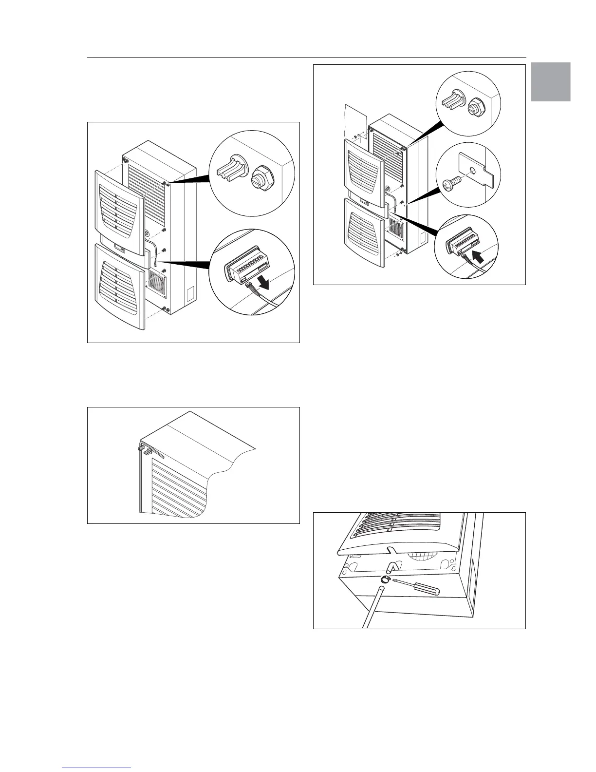
• Loosen the four nuts and washers from the front
enclosure half.
• Push the unit into the mounting cut-out from the
inside of the enclosure, and secure it to the en-
closure from the outside using the washers and
nuts.
Fig. 17: Secure the cooling unit
• Where necessary, additionally secure the unit
using the supplied mounting plates as shown in
Fig. 17.
• Carefully connect the display connector.
• Push the louvred grille and, where applicable,
the infill panel, onto the enclosure.
4.4 Connecting the condensate discharge
Unit types SK 3302.xxx, SK 3303.xxx and
SK 3361.xxx support the installation of a condensate
discharge hose (Ø
1
/
2
˝).
The condensate discharge
– must be laid with a suitable and constant gradient
(no siphoning)
– must be laid without kinks
– must not have a reduced cross-section if extended.
The condensate hose is available as an accessory
(refer also to Accessories in the RITTAL Catalogue).
Fig. 18: Connecting the condensate discharge
• Connect a suitable hose to the condensate nozzle
and secure using a hose clip.
• Lay the condensate hose into a pay-off or into the
external condensate evaporator (refer to accesso-
ries in the RITTAL Catalogue).
 Loading...