24 RITTAL cooling unit assembly and operating instructions
6 Operation
EN
6.1.2 Operating and error display
The Basic controller monitors and controls the cool-
ing unit. It indicates the operating and error status via
the green and red LEDs (Fig. 36, no. 3 and 4):
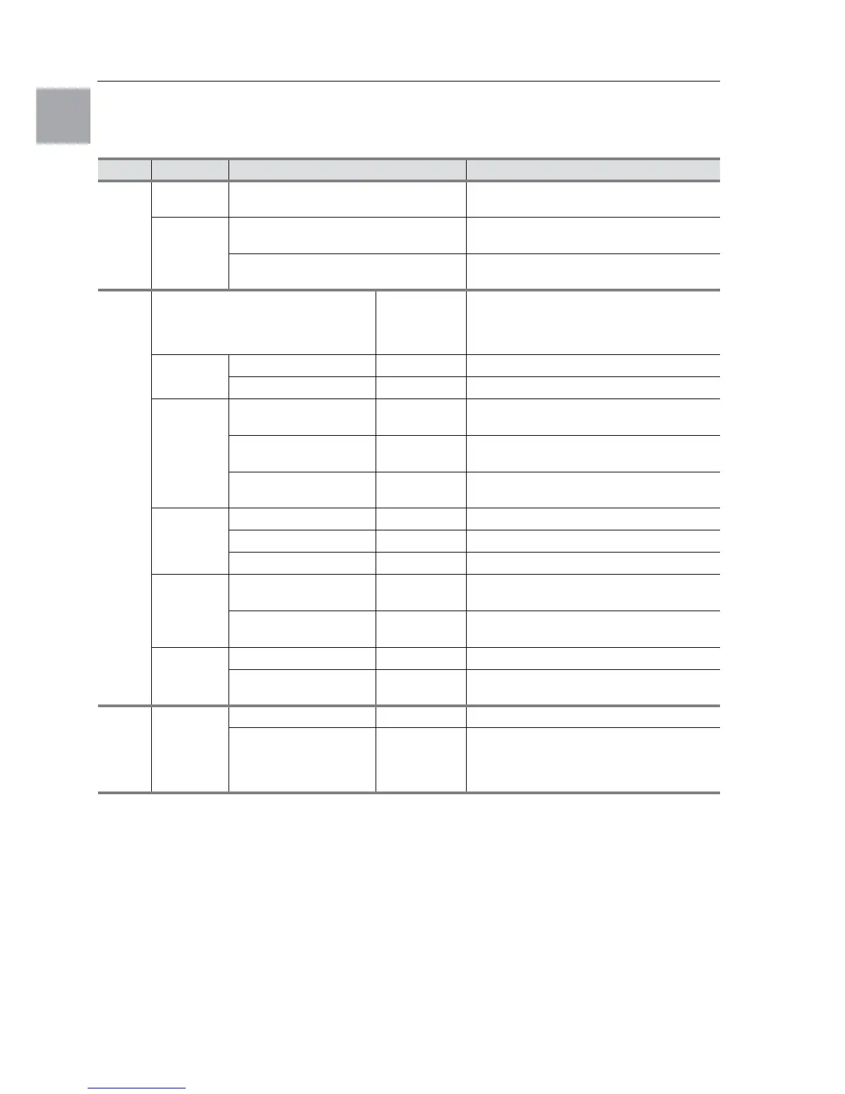
Tab. 3: Operating and error display of the Basic controller
Key to flash intervals
|=500 ms (red LED on)
_= 500 ms (red LED off)
***** = 3 s pause (red LED off)
LED Status Cause Solution
Green
(line)
Illuminated Voltage present,
unit operational
–
Flashing Only with door limit switch installed:
Enclosure door open
In order to avoid condensation, close the
enclosure door as quickly as possible.
Only with door limit switch installed:
Enclosure door closed
Check the position of the door limit switch.
Red
(alarm)
Alarm/error/warning Number of
flash intervals
for the red
LED
Flash interval
Implement
a reset
Device reset (12) |_|_|_|_|_|_|_|_|_|_|_|*****|_|_|_|_|_|_|_|_|_|_|_|
High pressure alarm (0) |_|_|_|_|_|_|_|_|_|_|_|_|_|_|_|_|_|_|_|_|_|_|_|_|_|
Sensors Potentiometer defective
or display error
(3) |_|_|*****|_|_|*****|_|_|*****|_|_|*****|_|_|*****
Interior temperature
sensor defective
(4) |_|_|_|*****|_|_|_|*****|_|_|_|*****|_|_|_|*****
Anti-icing sensor
defective
(5) |_|_|_|_|*****|_|_|_|_|*****|_|_|_|_|*****|_|_|_|_|
Overload Compressor overloaded (6) |_|_|_|_|_|*****|_|_|_|_|_|*****|_|_|_|_|_|*****
Interior fan overloaded (7) |_|_|_|_|_|_|*****|_|_|_|_|_|_|*****|_|_|_|_|_|_|
Exterior fan overloaded (8) |_|_|_|_|_|_|_|*****|_|_|_|_|_|_|_|*****
Device
status/
condition
Overload mode
(heat loss)
(9) |_|_|_|_|_|_|_|_|*****|_|_|_|_|_|_|_|_|*****
Low load mode
(heat loss)
(11) |_|_|_|_|_|_|_|_|_|_|*****|_|_|_|_|_|_|_|_|_|_|
Warning
(ambient
conditions)
Anti-icing alarm (2) |_|*****|_|*****|_|*****|_|*****|_|*****|_|*****|_|
Overtemperature
warning
(1) |*****|*****|*****|*****|*****|*****|*****|*****|*****|
Off No
display
No power – Check power supply
Rotary current phase
monitoring
:
“LED off” = Incorrect
phase connection
– Swap phases
 Loading...