14 RITTAL cooling unit assembly and operating instructions
4 Assembly and connection
EN
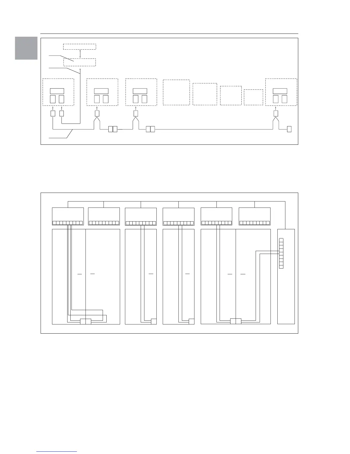
Fig. 19: Connection example: Master-slave operation
Legend
1 Serial interface (Model No. SK 3124.200)
2 Serial interface cable
3 Master-slave bus cable (Model No. SK 3124.100)
RTT RITTAL TopTherm cooling units
X1 Supply connection/door limit switch/alarms
X2 Master-slave connection Sub-D, 9-pole
X3 Serial interface Sub-D, 9-pole
St. Sub-D connector, 9-pole
Bu. Sub-D jack, 9-pole
Adr. Address
Fig. 20: Connection example: Door limit switch and master-slave operation
Legend
1 Master cooling unit
2 Slave cooling units
3 2-door enclosure with two door limit switches
4 Enclosure with door limit switch
4.6.3 Installing the power supply
• Complete the electrical installation by following
the wiring plan on the rear of the cooling unit
(see Fig. 1 on page 5, for key see page 21).
• If you would like the system messages from the
cooling unit to be evaluated via the system
message relay, you should also connect a suitable
low-voltage cable to connection clamps 3 – 5.
X2
CMC
I/O unit
RTT
Master
Adr.: 09
X1
X2
X3
X1
X2
X3
X1
X2
X3
X1
X2
X3
X2
X3
X2
X2
X2
X2
X2
X2
St. St. St.
Bu.
St.
Bu.
X2
Adr.: 11 Adr.: 12RTT
Slave
RTT
Slave
Adr.: 19RTT
Slave
St.
Bu.
St.
Bu.
3
2
1
X10
L1
L2
N
PE
1
23
4
5
1
X10
X10 X10 X10 X10
X2 X2 X2 X2 X2 X2
X2
L1
PE
1
23
4
5
L1
L2
N
PE
1
23
4
5
L2 L3
L1
PE
1
23
4
5
L2 L3
L1
PE
1
23
4
5
L2 L3
L1
PE
1
23
4
5
L2 L3
L1
L2
N
PE
1
23
4
5
X10
2
3
4
56
1
Adr.: 06 Adr.: 11 Adr.: 12 Adr.: 13 Adr.: 14 Adr.: 15
22 2 2 2
34432
Adr.: 16
 Loading...