Modbus RTU remote management.
LAN local network.
Refer to the wiring diagram.
6.2.1
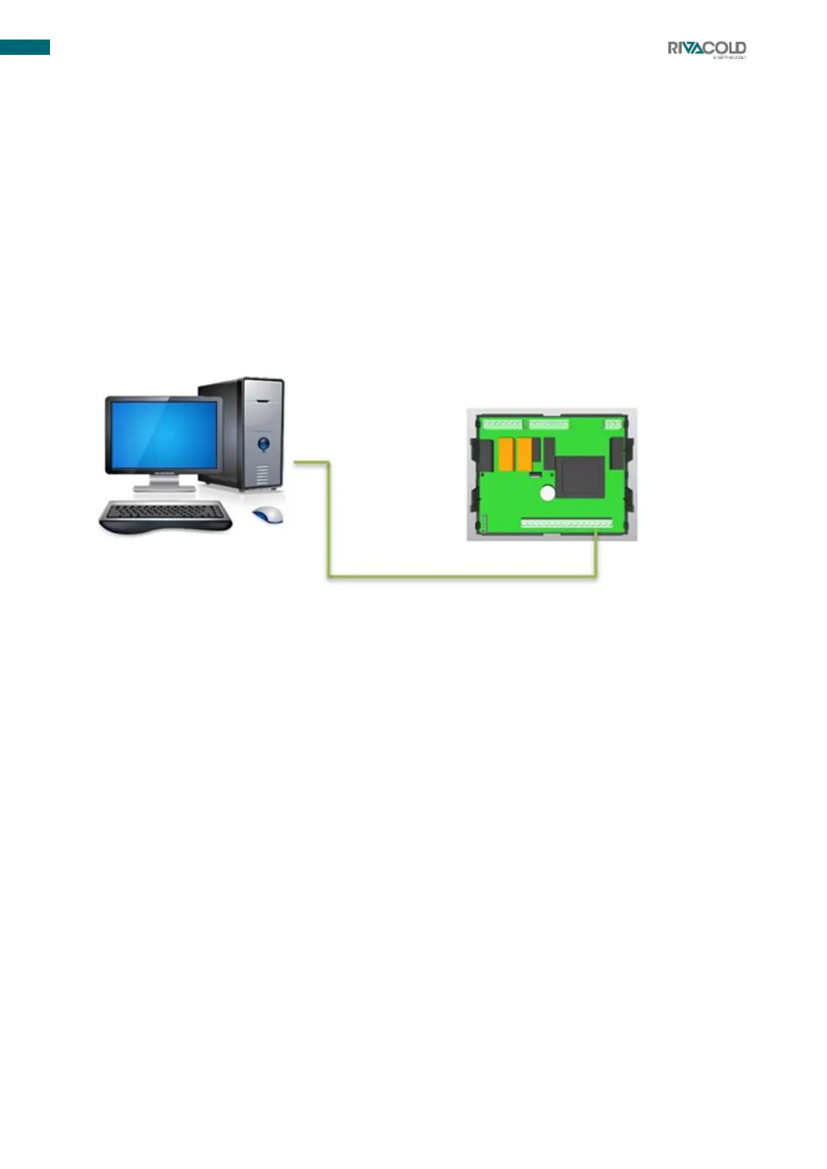
Remote management connection (Modbus RTU)
1.
Upload dedicated board template to your monitoring system. If you do not have the dedicated file, ask
your dealer for assistance.
2.
Use shielded braided cable.
3.
Connect to board pins 36(- ) and 37(+) .
4.
Change the Adr parameter identifying the serial address of the board in the Modbus RTU network if
required.
6.2.2
Local network (LAN) connection
Maximum of 8 electronic boards to manage defrosting cycles start/end synchronisation, setpoint
synchronisation, display synchronisation, light synchronisation and cold room probe synchronisation.
1.
Use shielded serial cable.
2.
Connect to board pins 38(- ) and 39(+) by making a serial connection (see connection photo
below).
3.
Enter the PR1 programming menu to change the following Lds and Lsd parameters and then define
the main unit/secondary units. Change the parameters written above according to the values in the
programming table enclosed with the unit.