16
4.5 ENGINE MAINTENANCE
The roadhog is equipped with a tier 4 interim
Deutz D2011L03i 49 hp air cooled engine.
Air filters should be checked daily.
Engine oil level should be checked daily. Always
check engine oil with the engine level.
An engine manual is included with each
Roadhog. Please refer to the engine manual for
maintenance intervals, recommended fluids and
procedures. If the engine manual is not available
contact RoadHog for a replacement.
Pay particular attention to:
1. Engine oil changes
2. Air filter changes
3. Fuel Filter changes
4. Oil Cooler cleaning
5. Valve adjustments
4.6 HYDRAULIC SYSTEM
If necessary add hydraulic fluid to the hydraulic
tank to the middle of the tank site glass. Fill the
tank with Hytran Ultra ( MS1209 ) hydraulic fluid
or equivalent. Always check the fluid level with
the RoadHog level. Ensure the filter and hydraulic
fluid is changed every 50 hours of operations.
4.7 WELDING PRECAUTIONS
Before welding on the roadhog disconnect the
engine controller from the RoadHog. This panel
is equipped with a computer and welding may
damage the controller.
Also, disconnect the main engine harness, locat-
ed on the left rear of the cylinder block on the en-
gine.
If welding on the drum ground directly to the
drum. Do no allow current to flow through the
dead shaft bearing or planetary gearbox. These
components could be damaged.
TO AVOID DAMAGE ALWAYS FOL-
LOW DISCONNECT PROCEDURE BE-
FORE WELDING. SEE SECTION 4.7
FOR WELDING PRECAUTIONS
IMPORTANT
4.8 STARTER INTERLOCK
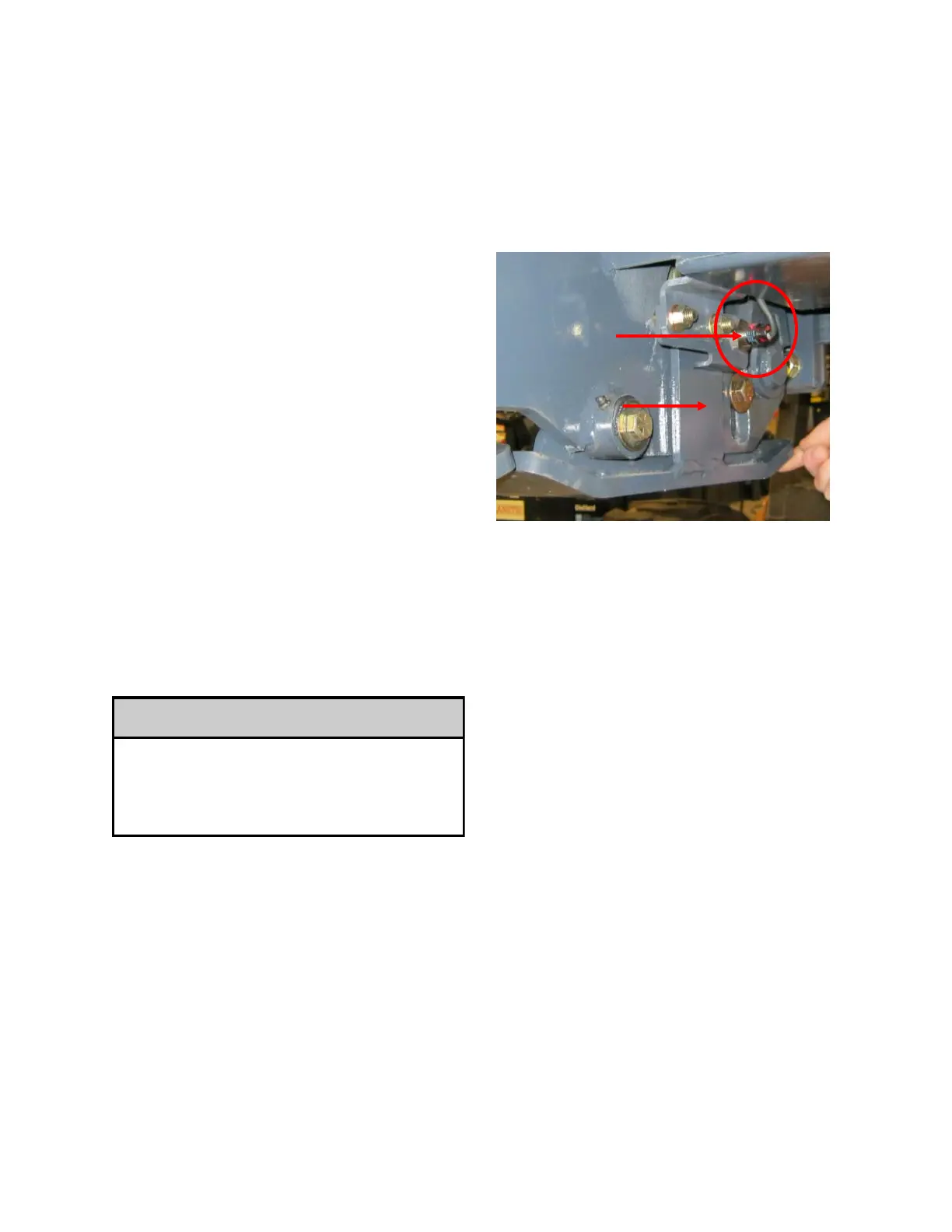
The roadhog is equipped with proximity switch
(prox) that disengages the engine starter if the
unit is sitting on the ground. The prox senses a
flag on a pivoting wear skid. Refer to image
below.
Proximity Sensor Specification:
- The prox switch has a sensing range of
8mm +/-10%(0.3125+/-10%).
- The prox has a red indicator light on the end
that shows if the prox is picking up the flag on the
wear skid.
Adjustment Procedure:
1. Raise the unit up off the ground unit you
can easily get to the prox switch.
2. Always use a safety block under the
machine or a safety chain before performing any
work.
3. The prox has two nuts that locks it in place.
4. Turn the starter switch 90 degrees but do
not start the engine. The switch need power to
light up the indicator light.
5. Hold or have someone hold up the pivoting
wear skid.
6. Loosen the locking nuts and move the prox
switch in towards the flag on the wear skid until
the indicator light illuminates.
7. Lock the prox switch in place with the two
jam nuts.
8. Once the prox switch is locked down
ensure the indicator light is still on and the head
of the prox is not touching the flag.
Prox Switch
Wear skid/flag



 To Next Page