Remove the parts from the box and match it with the parts list.
Make sure that the kit has all the parts shown on the parts list on
page 2.
Apply parking brake.
The following procedures can be done with the wheels of the ve-
hicle on the ground.
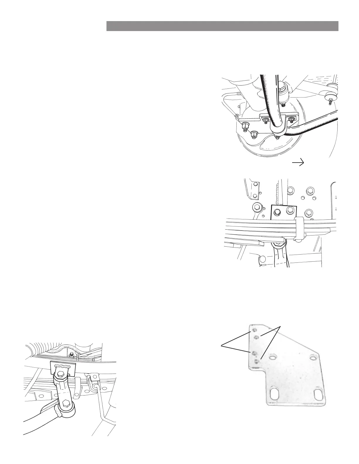
Locate u-bolts holding springs to axle.
Note: do not remove the factory anti-sway bar. This kit is designed
to support the factory anti-sway bar — not replace it. Remove nuts
from u-bolts on one side. Retain the factory axle bracket and add
a flat plate (B586) with small holes positioned toward front and
center of vehicle. Secure with the factory nuts and washers. Torque
to the manufacturer’s specifications. Repeat the process on the op-
posite side (Figure 1).
Install the saddle brackets and bushings on the anti-sway bar.
Lubricate the inside of the split bushings with the provided lubri-
cant. Install the bushings on the anti-sway bar near the arms. Slide
the saddle brackets over the split bushings.
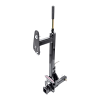
Install the anti-sway bar assembly to the flat plates.
Lift the anti-sway bar assembly into position so that the saddle
bracket holes align with the flat plate holes. Use the provided
bolts (350074-00), washers (350304-80) and nuts (350256-02)
to attach it. Tighten to 35-45 ft.-lbs. Note: for applications under
18,000lb GVWR, use the holes offset to the center of the plate.
For applications over 18,000lb GVWR, use the holes closest to the
edge of the plate (Figure 2).
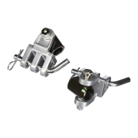
Locate shackles and fasteners.
Attach shackle (B285) to the anti-sway bar end with the provided
bolts (350158-00) and nuts (350263-00 — Figure 3). Do not
tighten yet.
INSTALLATION
The following instructions must be followed in the order listed to ensure a proper installation
and to preserve the ROADMASTER warranty.
Ford F-53 V10 Rear Anti-Sway Bar Kit • 5
1.
2.
4.
5.
6.
3.
Front
4
Figure 1
Figure 2
Figure 3
use for over
18,000lb
GVWR
use for under
18,000lb
GVWR
 Loading...