8
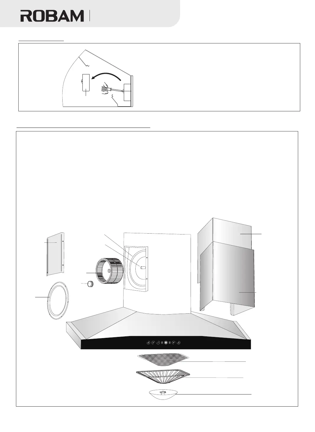
General Plan of Body Installation and Removal
Figure 28
Removal steps:
1. Pull out the plug;
2. Unscrew the four screws from the back of the decorative panel. Tilt the panel forward to a certain
angle, and then pull it up forcibly;
3. Remove the drawing panel from the decorative panel;
4. Use a Phillips screwdriver to unscrew the fastening screws on the cover to remove the cover;
5. Unscrew the fastening screws on the retaining ring to remove the retaining ring;
6. Unscrew the cap clockwise and take out the impeller vertically;
7. Remove the oil cup as shown in Figure 20 and then remove the filter mesh according to Figure 25-26.
The installation and removal procedure in reverse. (When mounting the impeller, apply some lubricant to
the shaft hole.)
Note: Step 3 is unnecessary if no drawing panel is installed.
Impeller
Cap
Air flue
Motor
Retainer ring
Cover pla te
Drawi ng panel
Decorative panel
Note: The light, filter mesh and switch shall be installed in a reverse order.
Switch Removal
Switch accessory
Figure 72
Oil cup
Filter mesh
Filter screen
吸油烟机
Range Hood
●
to remove the two screws on the switch. Push the
switch assembly diagonally upward to take it out
from the lamp hole for repair and replacement.
After removing the light, use a Phillips screwdriver
A818