4
504
Ceiling
6
6
0
(6
0
0
)
-8
0
0
m
m
6
5
0
-7
5
0
mm
8
0
0
-9
0
0
m
m
Drawing panel
10mm
Ceiling
Removable panel
Removable baffle
6
5
0
-7
5
0
mm
8
0
0
-9
0
0
m
m
10mm
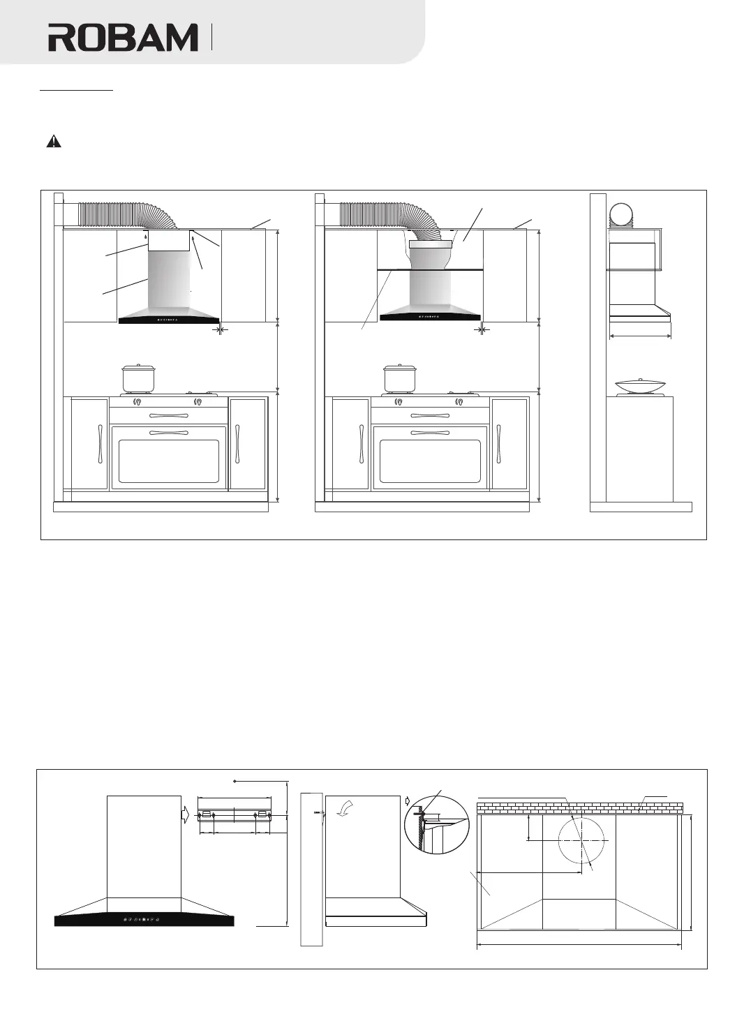
(Figure 9-1 Installation method of hood with removable baffle)
(Figure 9-2 Installation method of hood without removable baffle)
Mounting hole
of the drawing
panel
ST4X18 self-tapping
screws
(if installation method in Figure 9-2 is adopted, there' s no need to adjust and install the drawing panel)
CXW-20 0-8302
Decorative panel
Figure 10-1
35±2mm
Hitching foot stopper
235mm
65±2mm
Hitching foot
110mm
55mm 55mm
600(545) mm
Installation
(A818 and A809 are identical)
108mm
467mm
Wall
Hole size of the exhaust pipe Φ200mm
Ceiling drilling size chart
50 4 ( 524 ) mm
895mm
Figure10-2
Projection size of
the hood top
Size in brackets is specific to A809 hood
6
6
0
(
6
0
0
)
-
8
0
0
m
m
Note: Figures in brackets are specific to the cupboard size of A809 hood.
吸油烟机
Range Hood
1.Determine the position: the size of removable baffle ( reference: 430mm) can be adjusted according
to the actual situations. The installation pitch of holes is shown in Figure 10-1. The hook body shall be
centered vertically and kept level. Ceiling hole size is shown in Figure 10-2.
The hood shall be installed right above the hob. The minimum distance between the bearing surface
of cooking appliance and the lowest part of hood is 650mm (larger space specified in the installation
instruction of gas hob shall be considered, if any; the distance for electric cooker may be reduced
appropriately, depending on the actual situations) .
2. Install hitching foots: according to the size of the hitching foots, drill four 50-60mm-deep holes on the
wall accordingly with an 8mm-diameter drill bit ( overlarge holes are prohibited). Press the expansion
pipe into the holes, and then fix the hitching foots with 4 accompanying ST4.8×50 wood screws. At 65mm
above the four holes, drill a hole of 10mm-diameter and 40-45mm depth (overlarge holes are prohibited).
Insert the M6 metal expansion pipe into the hole. (As shown in Figure 10-1)
3. Adjust the drawing panel: pull the brackets of the panel up to an appropriate height and then pull the
panel sides to find the drawing panel. Remove the protective film, and insert it along the gap between the
decorative panel and the housing. Then adjust it to the proper height.
4. Install the hood body: fix the check valve as shown in Figure 11. Then direct the hanging holes in the
back of hood at the hooks of hitching foots according to Figure 10-1, and press them together. Shake the
body to check if it's hung securely. After the body is mounted, install the hitching foot stopper and gaskets to
the M6 metal expansion pipe, and then tighten the nuts ( to prevent accidental decoupling of the body
under external force).
5. Install the drawing panel: as shown in Figure 9-1, there are some gap between the drawing panel
and the top plate. Push the panel against the top plate and then fix it to the top plate with ST4×18 screws.
A818
A818
A818