5-
4-
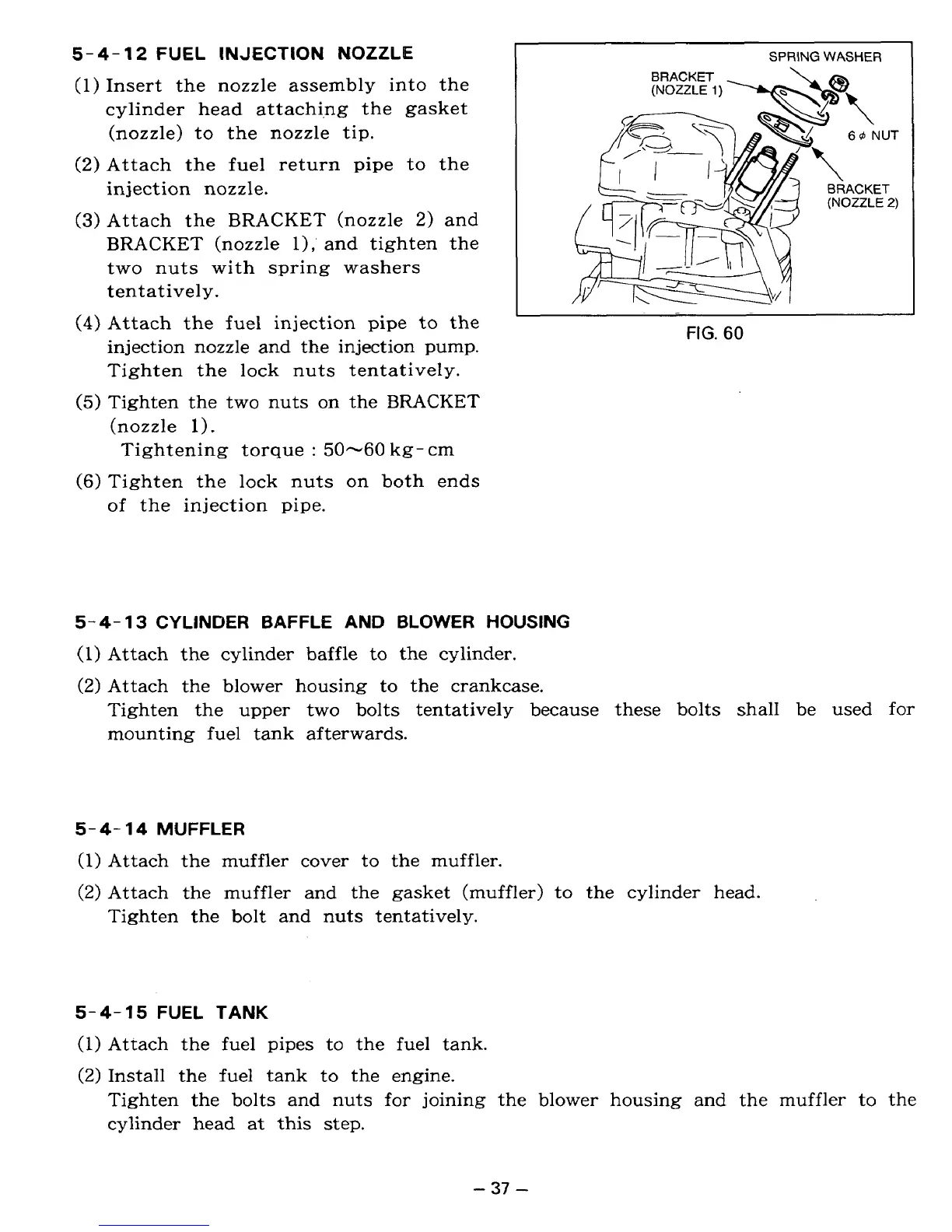
12
FUEL
INJECTION NOZZLE
(1)
Insert the nozzle assembly into the
cylinder head attachi-ng the gasket
V
(nozzle) to the nozzle
tip.
(2)
Attach the fuel return pipe to the
injection nozzle.
(3)
Attach the BRACKET (nozzle
2)
and
BRACKET (nozzle
l),'
and tighten the
two nuts with spring washers
tentatively.
(4)
Attach the fuel injection pipe
to
the
injection nozzle and the injection pump.
Tighten the lock nuts tentatively.
(5)
Tighten the two nuts on the BRACKET
(nozzle
1).
Tightening torque
:
50-60
kg- em
(6)
Tighten the lock nuts
on
both ends
of the injection pipe.
I
SPRING
WASHER
FIG.
60
5-4-
13
CYLINDER BAFFLE
AND
BLOWER HOUSING
lv
(I)
Attach the cylinder baffle to the cylinder.
(2)
Attach the blower housing to the crankcase.
Tighten the upper two bolts tentatively because these bolts shall be used for
mounting fuel tank afterwards.
5-4-
14
MUFFLER
(1)
Attach the muffler cover to the muffler.
(2)
Attach the muffler and the gasket (muffler) to the cylinder head.
Tighten the bolt and
nuts
tentatively.
5-4-15
FUEL TANK
(1)
Attach the fuel pipes to the fuel tank.
(2)
Install the fuel tank to the engine.
I
Tighten the bolts and nuts for joining the blower housing and the muffler to the
cylinder head at this step.
-
37
-
 Loading...