4.
Refer to Figure
5-4.
Insert a screwdriver in slot at
end of governor shaft. Turn clockwise as far as
shaft can be turned. Tighten governor lever
clamp screw.
1
GOVERNOR
SHAFT
GOVERNOR
LEVER
TIGHTENING BOLT
:igure
5-4.
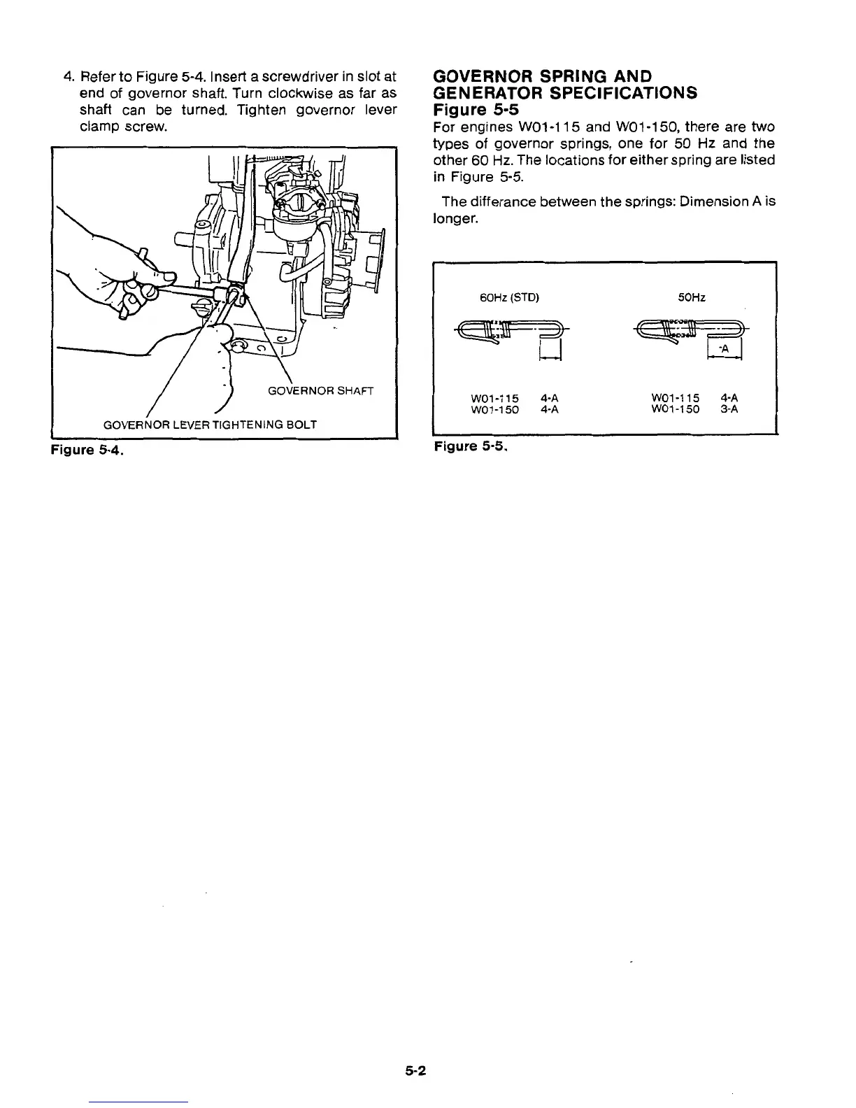
GOVERNOR SPRING AND
GENERATOR SPECIFICATIONS
Figure
5-5
I'
For engines WO1-115 and WO1-150, there are
two
types of governor springs, one for
50
Hz
and the
other
60
Hz.
The locations for either spring are listed
in Figure
5-5.
The differance between the springs: Dimension
A
is
longer.
60Hz
(STD)
50Hz
I
WO1-115
4-A
WO1-150
4-A
WO1-115
4-A
WO1-150
3-A
L
Figure
5-5.
/"
5-2
 Loading...
