IDLE
SYSTEM
Figures 6-1
and
6-2
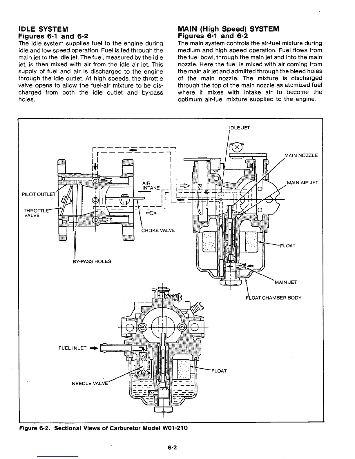
The idle system supplies fuel to the engine during
idle and low speed operation. Fuel is fed through the
main jet to the idle jet. The fuel, measured by the idle
jet, is then mixed with air from the idle air jet. This
supply of fuel and air is discharged to the engine
through the idle outlet. At high speeds, the throttle
valve opens to allow the fuel-air mixture to be dis-
charged from both the idle outlet and by-pass
MAIN
(High
Speed)
SYSTEM
Figures 6-1
and
6-2
The main system controls the air-fuel mixture during
r
medium and high speed operation. Fuel flows from
the fuel bowl, through the main jet and into the main
nozzle. Here the fuel is mixed with air coming from
the main air jet and admitted through the bleed holes
of
the main nozzle. The mixture is discharged
through the top
of
the main nozzle as atomized fuel
where it mixes with intake air
to
become the
holes. optimum air-fuel mixture supplied to the engine.
BY-PASS
HOLES
Figure
6-2.
Sectional Views
of
Carburetor
Model
WO1-210
6-2
 Loading...