ENGINE REPAIR
1
Part
No.
Description
I
w.
EY2099500407
1
Flywheel
Puller
w/Bolts
1
1
PREPARATION AND SUGGESTIONS
Provide a well lighted working area with enough
space for parts and tools to be spread out.
A
work
stand is essential for holding the engine securely.
When disassembling the engine, lay parts out in the
order they were removed. Have several boxes avail-
able
so
that parts belonging to certain groups can be
kept together. Tag parts if there is a possibility of
confusion.
Use the PARTS MANUAL for reference during
reassembly. The exploded view illustrations will help
identify parts, show the components of individuaf
assembly groups and
show
the order of
reassembly.
Often it
is
not necessary to disassemble the entire
engine. The instructions contained in this manual are
arranged by components. If entire engine dis-
assembly is required, locate the reassembly instruc-
tions under headings of the various parts.
NOTE:
Drain oil from crankcase before disas-
se
m bly.
While the engine is partly or fully dismantled, clean
and inspect all parts and replace as needed. During
reassembly use new gaskets and lubricate all bear-
ing surfaces.
Torque parts
to
specifications where given
(see
‘SPECIFICATIONS’). Use caution in tightening all
other screws and nuts to avoid stripping threads or
breaking flanges.
-
DISASSEMBLY
AND
REASSEMBLY
-
Air
Cleaner
MODELS
WO1-115
AND
WO1-150
1.
Remove air cleaner cover and element.
2.
Remove air cleaner base from carburetor.
Remove breather pipe.
AND
OVERHAUL
3.
Remove front cover from blower housing.
4.
During reassembly refer
to
air cleaner main-
tenance instructions. (See ‘MAINTENANCE
SC
H
ED U LE.’)
Control Panel
1.
Disconnect switch lead from connector.
2.
Remove panel from cylinder head and
carburetor.
3.
Remove choke knob from shaft.
Muffler
Remove muffler cover, muffler and heat deflector
from crankcase.
During reassembly note the direction of the
muffler gasket.
Recoil
Starter
and
Blower Housing
1.
Remove recoil starter assembly.
2.
Inspect condition of rope. (See Starting System
section if replacement is needed).
3.
Remove blower housing from crankcase and
cylinder head.
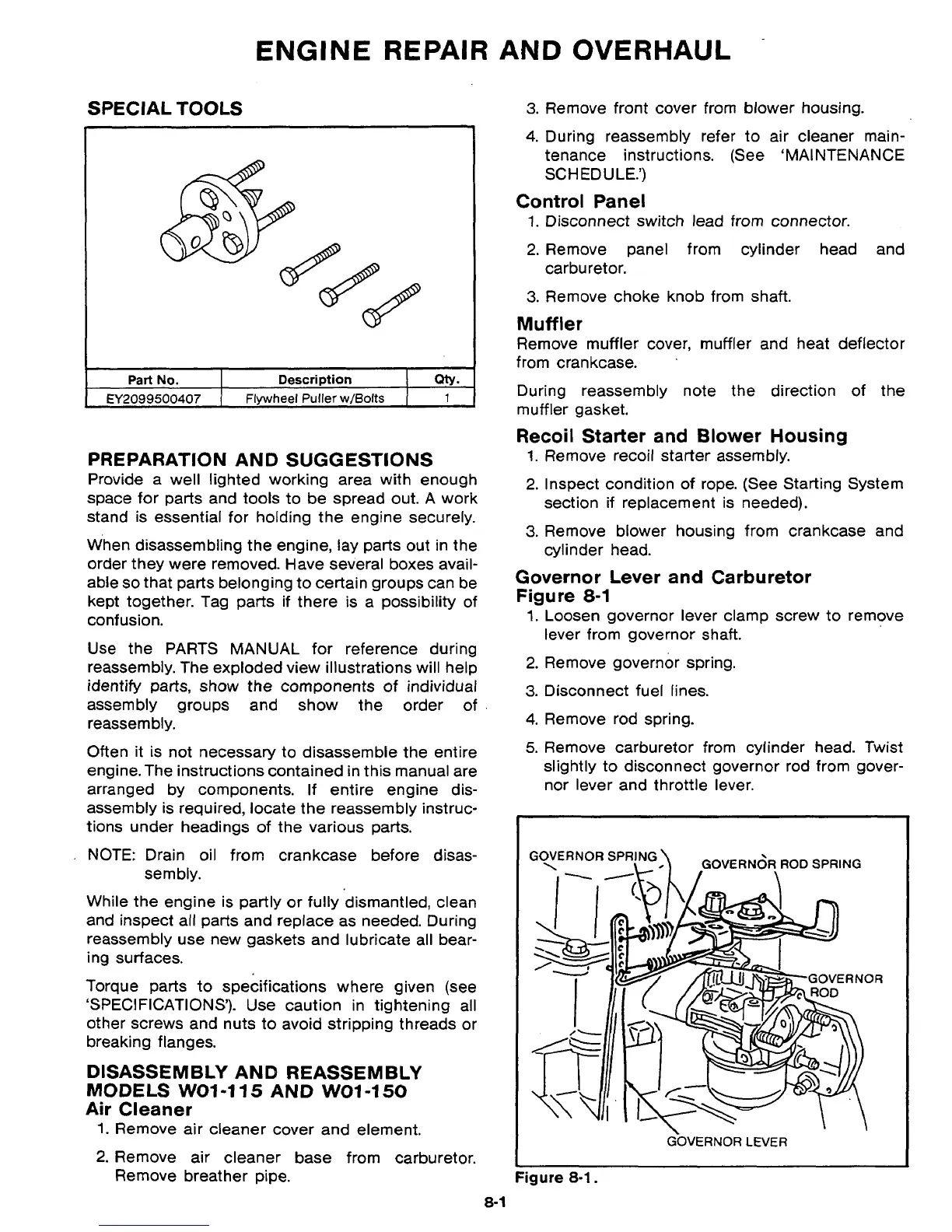
Governor Lever and Carburetor
Figure
8-1
1.
Loosen governor lever clamp screw to remove
lever from governor shaft.
2.
Remove governor spring.
3.
Disconnect fuel lines.
4.
Remove rod spring.
5.
Remove carburetor from cylinder head. Twist
slightly to disconnect governor rod from gover-
nor lever and throttle lever.
\
GOVERN~R
ROD
SPRING
I
GOVERNOR
LEVER
Figure
8-1.
8-
1
 Loading...