Choke System
Figures
6-3
and
6-4
1.
Remove screws to remove choke valve and
choke shaft. Use care to avoid damaging
parts.
2.
During reassembly, install with cut-out on valve
facing main air jet.
Idle
System
Figures
6-3
and 6-4
1.
Remove idle jet. Use care to avoid damaging
parts.
NOTE: Idle jet is included in repair kit.
2.
During reassembly, tighten idle jet securely to
prevent fuel leakage.
Main
Fuel System
Figures
6-3
and 6-4
1.
Drain remaining fuel in fuel bowl into a suitable
container. Remove bowl and gasket.
2.
Remove main jet from carburetor body.
NOTE: Main jet is included in repair kit.
3.
During reassembly, tighten main jet securely to
prevent fuel mixture from becoming too rich.
Install fuel bowl and new gasket. Torque screw to
specifications (see 'SPECIFICATIONS').
Float System
Figures
6-3
and 6-4
1.
Remove float pin, float and needle valve.
NOTE: Float pin is flattened at one end. Use a small
drift punch and tap on float pin round end
to remove.
r
2.
Inspect float. Replace
if
dented, contains fuel, or
if
float
axle
bearing and tab contacting needle
valve are worn excessively.
NOTE: Special service needle valve is included in
repair kit.
Inspect needle valve. Replace
if
damaged or worn.
3.
During reassembly, adjust float setting. With float
chamber bowl removed, place carburetor body
on end. Float surface must be parallel to car-
buretor body. To adjust float surface bend tab.
The tab (float lever) should just contact the fuel
needle valve.
Install float bowl using a new gasket. Torque to
specifications (see 'SPECIFICATIONS).
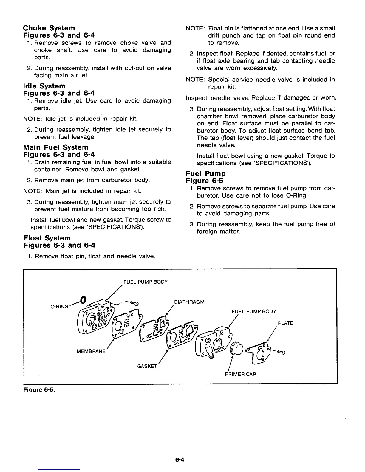
Fuel Pump
Figure
6-5
1.
Remove screws to remove fuel pump from car-
buretor. Use care not to lose 0-Ring.
2.
Remove screws
to
separate fuel pump. Use care
to avoid damaging parts.
3.
During reassembly, keep the fuel pump free of
foreign matter.
"
FUEL
PUMP BODY
O-RING
DIAPHRAGM
MEMBRANE
GASKET
PRIMER CAP
Figure
6-5.
,."
64
 Loading...