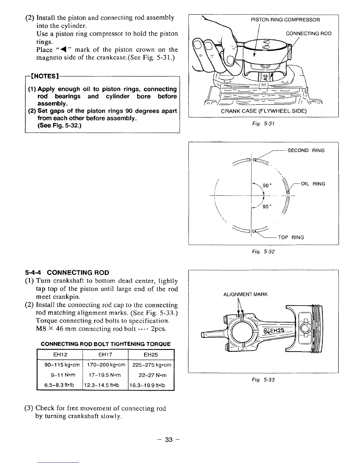
(2)
Install the piston
and
connecting
rod
assembly
into the cylinder.
Use
a
piston ring compressor to hold the piston
rings.
Place
‘‘4
”
mark
of the piston crown on the
magneto side of
the
crankcase.(See Fig.
5-31.)
-[NOTES]
1
(1)
Apply enough oil to piston rings, connecting
rod bearings and cylinder bore before
assembly.
(2)
Set gaps
of
the
piston
rings
90
degrees apart
from each other before assembly.
(See Fig.
5-32.)
5-4-4
CONNECTING
ROD
(1)
Turn crankshaft
to
bottom
dead
center, lightly
tap
top
of
the piston
until
large end
of
the
rod
meet crankpin.
(2)
Install
the
connecting
rod
cap
to
the connecting
rod matching alignment marks. (See Fig.
5-33.)
Torque connecting rod
bolts
to
specification.
M8
X
46
mm
connecting
rod
bo1
t
....
2pcs.
CONNECTING
ROD
BOLT
TIGHTENING TORQUE
I
EH12
I
EH17
I
EH25
I
90-1
15
kg*cm
22-27 Nom
17-19.5 Nom
9-11
N-m
225-275
kgocrn
170-200 kg-cm
6.5-8.3
ft*lb
16.3-19.9
ft4b
12.3-1
4.5
ftdb
PISTON RING COMPRESSOR
CONNECTING
ROD
CRANK CASE (FLYWHEEL
SIDE)
Fig.
5-31
-SECOND
RING
\
Fig.
5-32
ALIGNMENT MARK
h
Fig.
5-33
B
(3)
Check
for
free movement
of
connecting
rod
by
turning crankshaft slowly.
-
33
-