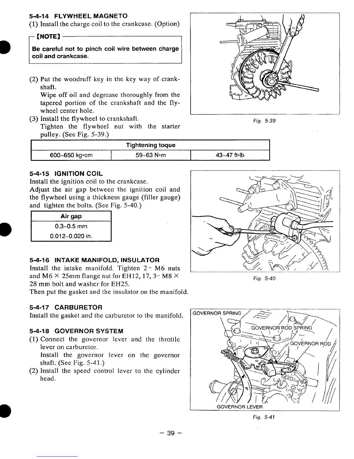
5-4-14
FLYWHEEL
MAGNETO
(1)
Install the charge coil
to
the crankcase. (Option)
-
[NOTE)
B
Be careful not to pinch
coil
wire between charge
coil
and crankcase.
(2)
Put the woodruff key
in
the key way of crank-
shaft.
Wipe
off
oil and degrease thoroughly from the
tapered portion
of
the crankshaft and the
fly-
wheel center hole.
Tighten the flywheel
nut
with
the starter
pulley. (See
Fig.
5-39.)
(3)
Install
the
flywheel
to
crankshaft.
Fig.
5-39
I
Tightening toque
I
600-650
kg*cm
43-47
ft*lb
59-63
Nom
5-4-15 IGNITION COIL
Install
the
ignition coil to the crankcase.
Adjust
the air gap between
the
ignition coil and
the flywheel using
a
thickness gauge (filler gauge)
and tighten the bolts. (See Fig.
5-40.)
I
Air
gap
I
0.3-0.5
mm
0.012-0.020
in.
5-4-16 INTAKE
MANIFOLD,
INSULATOR
Install the intake manifold. Tighten
2-
M6
nuts
and
M6
X
25mm flange
nut
for
EH12,17,3-
M8
X
28
mm
bolt and washer for
EH25.
Then put the gasket and the insulator on the manifold.
Fig.
5-40
5-4-17 CARBURETOR
Install the gasket and the carburetor to the manifold.
54-18
GOVERNOR
SYSTEM
(1)
Connect the governor lever
and
the throttle
lever
on
carburetor.
Install the
governor
lever
on
the governor
shaft. (See
Fig.
5-41.)
(2)
Install the speed control lever to the cylinder
head.
GOVERNOR LEVER
Fig.
5-4
1
-
39
-