-
33
-
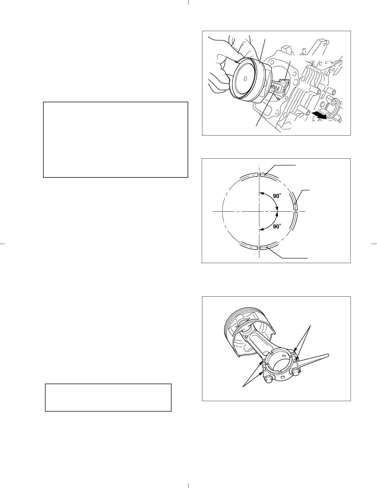
(2) Install piston and connecting rod assembly
into cylinder.
Use a piston ring compressor to hold piston
rings.
The “FAN” mark of the connecting rod is to
face flywheel side when assembled.
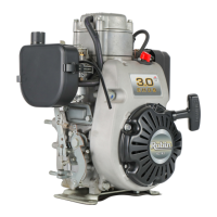
5-4-4 CONNECTING ROD
(1) Turn crankshaft to bottom dead center, lightly
tap top of the piston until large end of the rod
meet crank pin.
(2) Install connecting rod cap to connecting rod
matching alignment marks.
Torque connecting rod bolts to specification.
M8 x 40 mm connecting rod bolt : 2 pcs.
(3) Check for free movement of connecting rod
by turning crankshaft slowly.
Note:
(1) Apply enough oil to piston rings, con-
necting rod bearings and cylinder
bore before assembly.
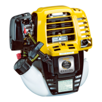
(2) Set gaps of the piston rings 90 de-
grees apart from each other before
assembly.
Fig. 5-29
Fig. 5-30
Fig. 5-31
Tightening torque : 22.1 - 27.0 N・m
(225 - 275 kgf・cm)
(16.3 - 19.9 ft
・lb.)
"FAN"MARK
PISTON RING COMPRESSOR
CONNECTING ROD
CRANKCASE
(
FLYWHEEL SIDE
)
SECOND RING
OIL RING
TOP RING
ALIGNMENT MARKS
ALIGNMENT MARKS