6-3-11
CONNECTING
ROD
and
PISTON
1)
Straighten
out
the
bent
tabs
of
rod lock washer and remove
bolts
from connecting rod.
2)
Take off
oil
scraper, rod
lock
washer and connecting
rod
cap..
3)
Scrape off
all
carbon deposits
that
might interfere with removal
of
piston from upper end of
4)
Turn crankshaft until piston is
at
top, then
push
connecting
rod
and piston assembly
upward
5)
Remove piston from connecting rod by taking out
two
clips and then removing
the
piston
6)
Remove piston rings from piston by widening
the
open ends.
cylinder.
and
out
through top
of
cylinder.
pin.
7)
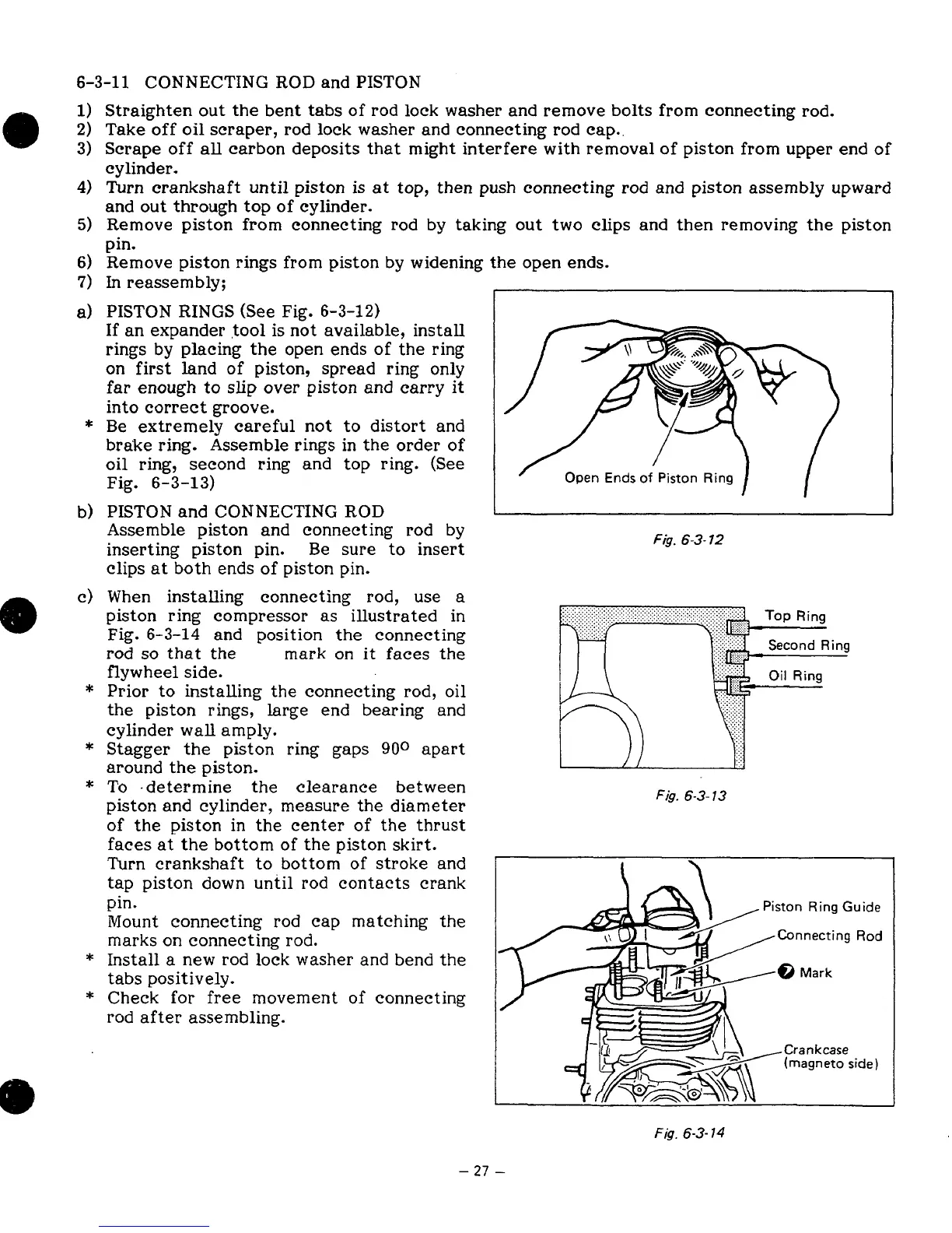
a)
b)
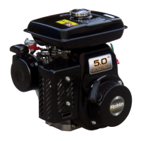
*
*
In
reassembly;
PISTON RINGS (See Fig.
6-3-12)
If an expander
tool
is not available, install
rings by placing the open ends
of
the
ring
on first land
of
piston, spread ring only
far enough
to
slip
over piston and carry it
into correct groove.
Be extremely careful not
to
distort and
brake ring. Assemble rings in
the
order
of
oil
ring, second ring and top ring. (See
Fig.
6-3-13)
PISTON and CONNECTING
ROD
Assemble piston and connecting rod
by
inserting piston pin. Be sure
to
insert
clips
at
both ends of piston pin.
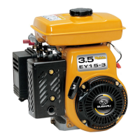
When installing connecting rod, use
a
piston ring compressor
as
illustrated in
Fig.
6-3-14
and position
the
connecting
rod
so
that
the
mark
on
it
faces
the
flywheel side.
Prior
to
installing
the
connecting rod, oil
the piston rings, large end bearing and
cylinder wall amply.
Stagger the piston ring gaps
900
apart
around
the
piston.
To
.determine
the
clearance between
piston and cylinder, measure the diameter
of
the piston in the center
of
the
thrust
faces
at
the bottom
of
the piston skirt.
Turn crankshaft
to
bottom of stroke and
tap piston down until rod contacts crank
pin.
Mount connecting rod cap matching
the
marks on connecting rod.
Install
a
new rod
lock
washer
and
bend the
tabs
positively.
Check
for
free
movement
of
connecting
rod after assembling.
Fa.
6-3-
12
.......
.......
.......
.......
!"&
Oil
Ring
.......
F
is.
6-3-
13
/I
I
F
is.
6-3-
13
Second
Ring
...
...
...
Piston
Ring
Guide
Fig.
6-3-
14
-
27
-