Roboguard 19
PROGRAM MODE D: OUTPUT PORT PROGRAMMING
The HQ can be connected to your alarm panel using the ‘Tele-cable’
provided with your purchase. You can change the HQ outputs to the
panel depending on the number of panel zones available to you.
Output Format 1: Monitor all Roboguards separately.
Output Format 2: All Roboguards report to a single panel zone.
Both Output Formats can be selected to trigger either NORMALLY OPEN
or NORMALLY CLOSED circuits.
To enter the programming mode:
1. Disconnect 12Volt power and the battery after opening the HQ.
2. Hold down both the Tamper and Status buttons and connect the
12Volt power supply until you hear a beep. Release the buttons.
Both red lights will flash and the default Setting 3, ON.
3. Select a Setting 1,2,3,4 from the two tables.
4. Press and release the Tamper button to accept. HQ will beep 10
times and all the lights will flash. Reconnect the battery and replace
the cover.
The HQ output wires (white to green) use transistors rated at a
maximum of 40mA which is sufficient to switch a relay, timer board or
alarm panel. For most alarm panel connections (usually N/C), the HQ
zone wire is connected through the in-line resistor of the spare panel
zone. The blue is common and should always be connected to
the battery –VE or common of anything that has its own power
source.
To check the switching put your multi-meter on Ohms, and measure
the resistance between ground (blue wire) and the desired wire (white
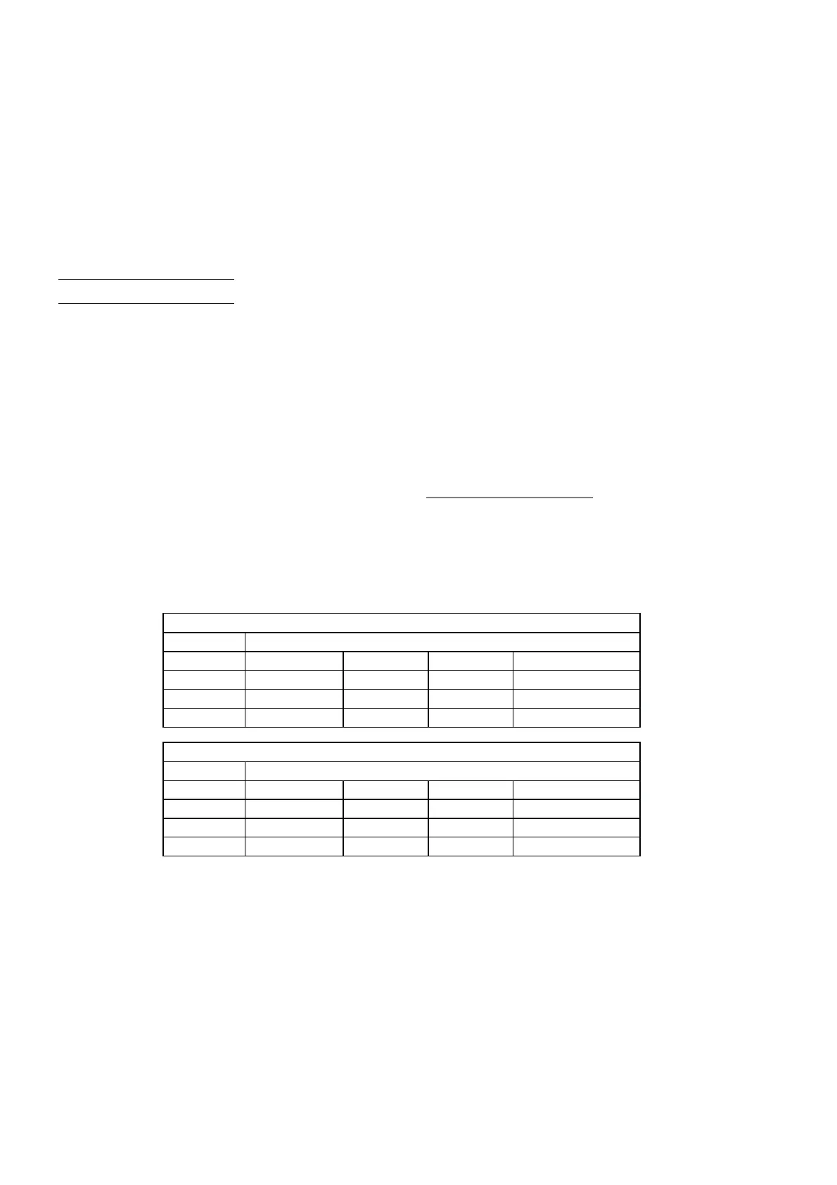
OUTPUT FORMAT 1
Setting 1= N/O Setting 3 = N/C (Default)
White Zone 1
Black Zone 2
Red Zone 3
Green Zone 4
OUTPUT FORMAT 2
Setting 2= N/O Setting 4 = N/C
White Zone1234
Black Tamper
Red Status
Green Panic/Silent