Roboguard 39
Configuration
There are no configurable options in this unit.
Testing
The installation must be tested for compatibility with the siren as the
siren control line is very noisy and may require additional filtering.
Note: Intruder zones on the receiver will only accept Roboguard Code
and Remote zones on the receiver will only accept Remote Code.
Now Trigger the device connected to the uTx to allow it to send a signal
to the receiver and register itself in the zone.
Continue with the next device.
Ensure all your devices are in their passive state and turn Switch 2
OFF.
Leave Switch 3 ON if you are transmitting Remote Code.
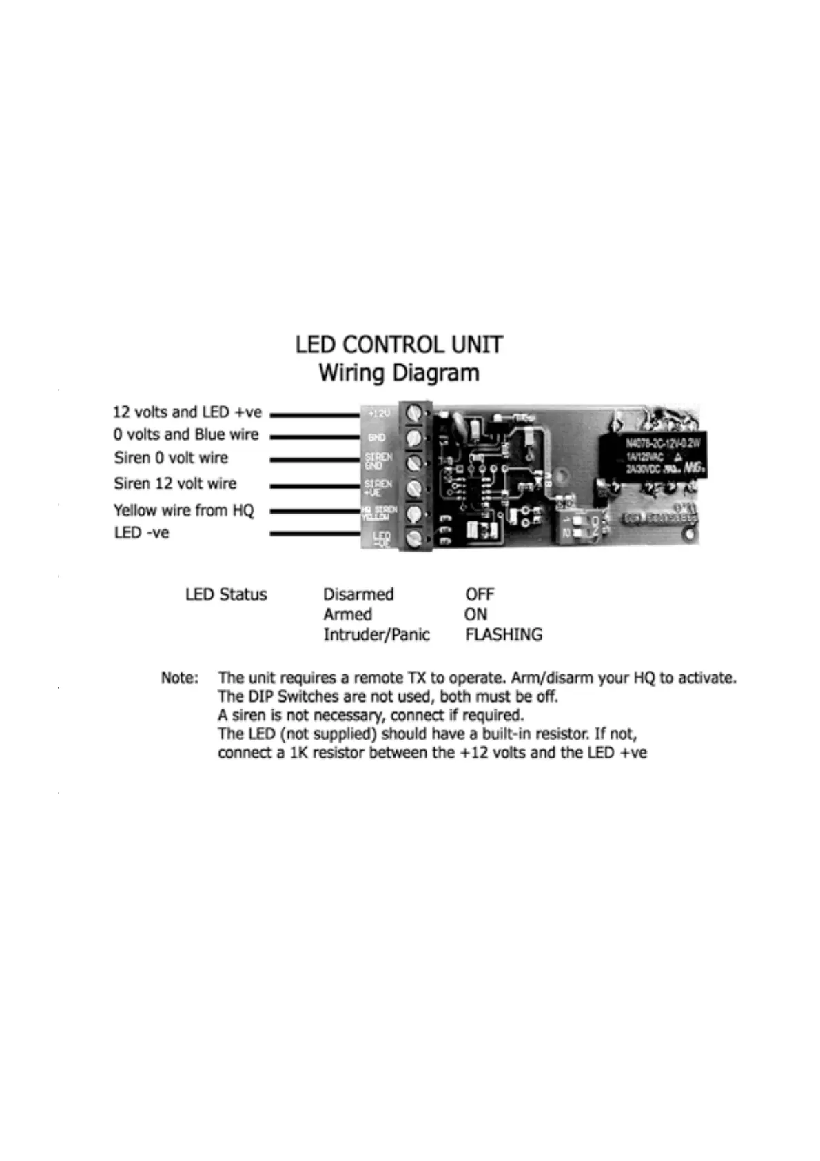
Wiring the board as packaged: Connect GND (0V) to Blue wire from
HQ, -VE on power supply and -VE on Siren (if used). Connect IO2 via
block to HQ yellow (trigger) wire. Connect relay 12V out via block to
Siren +VE (if used). Connect your LED between +12 V with resistor
and NC. Connect +12V to power supply; The LED will flash until the HQ
has been armed by remote, and thereafter operate normally.