EasyManua.ls Logo

RoboSense LiDAR RS-Helios-16P User Manual

RoboSense LiDAR RS-Helios-16P
62 pages
To Next Page IconTo Next Page
Page #1 background imageLoading...
Page #1 background image
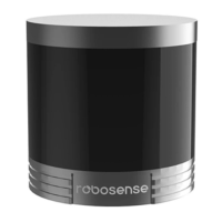
RS-Helios-16P User Manual
RS-Helios-16P

Table of Contents

Questions and Answers:

RoboSense LiDAR RS-Helios-16P Specifications

General IconGeneral
Number of Channels16
Wavelength905 nm
Range (80% reflectivity)up to 150m
Field of View (Horizontal)360°
IP RatingIP67
Power Supply9-32 V DC
Range150 m
Field of View (Vertical)30°
Horizontal Resolution0.1°
Frame Rate5 Hz, 10 Hz, 20 Hz
Scan Rate20 Hz
Data InterfaceEthernet
Operating Temperature-20°C to +60°C

Summary

Revision History

Terminologies

Manufacturer Information

Disclaimer of Liability

Certifications

Safety Notices

Laser Safety

Standards and precautions for laser product safety.

General Safety Instructions

Instructions for retaining, heeding warnings, and servicing.

Helios Series Products

Product Appearance and Interface

Product Appearance

Visual description and coordinate system of the LIDAR.

Aviation Plug and Pin Definition

Details of the aviation plug's pins and their functions.

Interface Box Overview

Description of the interface box, its LEDs, and connectivity.

Interface Box Power and Ports

Details on power supply, RJ45 Ethernet, and GPS interfaces.

Interface Box GPS Port Definition

Defines the pins and functions for the GPS port.

Unboxing & Installation

Standard Package Contents

Lists the items included in a standard factory package.

Sensor Mounting Procedure

Details on how to mount the LIDAR sensor, including screws and pins.

Mounting Requirements and Rigidity

Screw specs, flatness, pin height, and bracket rigidity requirements.

Quick Connection Guide

How to configure network settings and establish communication.

Sensor Specifications and Features

Sensor Specification Parameters

Detailed technical parameters of the sensor.

Point Cloud Display

Ranging Capability per Channel

Table showing vertical angles and range capabilities per channel.

Coordinate Mapping for Point Cloud

Formulae for converting polar to Cartesian coordinates for point cloud.

Reflectivity

Laser Return Modes

Laser Return Modes Principle

Explains different laser return modes and their impact.

Return Mode Flag Mapping

Table mapping flags to specific return modes.

Phase Locking

Phase Locking Settings Illustration

Illustrates different phase settings for the sensor.

Time Synchronization Methods

GPS Time Synchronization Process

Details the process of synchronizing time using GPS signals.

GPS Receiver Interface Usage

Explains how the GPS_REC interface is used for time sync.

GPS Receive Pin Definitions

Details the pin definitions for the GPS receive interface.

GPRMC Data Sentence Structure

Standard format of the GPRMC sentence used for GPS data.

PTP Time Synchronization Overview

Explains Precision Time Protocol for high-precision synchronization.

PTP Synchronization Wiring Method

Compares PTP advantages and outlines wiring steps.

Communication Protocol

Protocol Overview (MSOP & DIFOP)

Details the MSOP and DIFOP protocols used for communication.

MSOP and DIFOP Packet Structures

Explains the structure of MSOP and DIFOP UDP packets.

MSOP Header Structure Details

Details the fields and structure of the MSOP packet header.

MSOP Data Blocks (Single Return)

Describes the structure of data blocks in MSOP packets.

MSOP Data Blocks (Dual Return)

Describes the structure of data blocks in MSOP packets.

Channel Data Format Description

Details the format of distance and reflectivity data within a channel.

MSOP Packet Analysis

Calculate Distance from Data

Steps to calculate distance from MSOP packet data.

Calculate Azimuth from Data

Steps to calculate azimuth from MSOP packet data.

Azimuth Value Description

Explains how azimuth values are recorded and their resolution.

Azimuth Value Interpolation Method

Method for interpolating azimuth values for missing sequences.

MSOP Tail Structure Details

Details the structure of the MSOP packet tail.

Device Info Output Protocol (DIFOP)

DIFOP Packet Structure Details

Details the structure and fields of a DIFOP packet.

Vertical Angles and Point Time Calculation

Channel Number and Vertical Angle Mapping

Describes the vertical field of view and channel mapping.

Exact Point Time Calculation Method

Explains how to calculate the exact timing of laser points.

Troubleshooting

Troubleshooting Common Issues

Lists common issues like LED status, motor rotation, and data output problems.

Troubleshooting Frequent Data Dropouts

Troubleshooting steps for intermittent data loss.

Troubleshooting Sync Issues

Solutions for problems with GPS or PTP time synchronization.

Troubleshooting Data Output & Display

Addresses issues like no output or incorrect point cloud display.

Web Interface Operation

Web Interface: Device Information

Displays current LiDAR status and version information.

Web Interface: Parameter Settings

Allows configuration of IP, ports, return mode, and other parameters.

Web Interface: Diagnostic Screen

Monitors real-time sensor status like voltage, current, temp, and speed.

Web Interface: System Upgrade

Allows updating firmware for top board, bottom board, software, web, and motor.

Web Interface: Firmware Update Process

Describes the steps and confirmation of a successful firmware update.

Information Registers

Information Registers: Motor Speed & Ethernet

Defines registers for motor speed, IP addresses, MAC address, and ports.

Info Registers: Firmware Versions & Angles

Registers for firmware versions and corrected angles.

Info Registers: Corrected Vertical Angle Details

Details the structure and calculation for corrected vertical angles.

Info Registers: Horizontal Angle & Serial Number

Registers for corrected horizontal angles and the LiDAR serial number.

Info Registers: Status & UTC Time

Registers for monitoring current status like voltage and UTC time.

Info Registers: Status Details

Details calculation formulas for voltage and other status parameters.

Info Registers: Fault Diagnosis Registers

Registers for fault diagnosis, including temperature and status indicators.

Info Registers: Fault Diagnosis Details

Details GPS and status bit definitions for fault diagnosis.

Info Registers: GPRMC Packet Format

Describes the ASCII format of GPRMC data packets.

RSView Software Usage

RSView: Software Features

Lists capabilities of RSView for data acquisition and visualization.

RSView: Software Installation

Instructions for downloading and installing the RSView software.

RSView: Network Setup

Steps to configure network settings for RSView to connect to the LiDAR.

RSView: Visualize Streaming Data

Guide on how to connect and view live sensor data in RSView.

RSView: Capture Streaming Data to PCAP

Steps to record and save streaming sensor data into a PCAP file.

RSView: Replay Captured Data

How to replay and analyze previously saved PCAP files in RSView.

RSView: Set Data Port

How to configure RSView to use the correct MSOP and DIFOP port numbers.

ROS&ROS2 Integration

ROS/ROS2 Integration: Software Installation

Steps to install Ubuntu, ROS, ROS2, and libpcap-dev.

ROS/ROS2 Integration: Compile Driver

Instructions for obtaining and compiling the RoboSense LiDAR driver package.

ROS Integration: Compilation Steps

Steps for compiling the driver package in a ROS environment.

ROS2 Integration: Compilation Steps

Steps for compiling the driver package in a ROS2 environment.

ROS Integration: Configure PC IP

Steps to set the computer's IP address for ROS/ROS2 connection.

ROS Integration: Real Time Display

Guide to displaying point cloud data in real time using ROS.

ROS Integration: View Offline Data

Instructions for parsing and displaying offline PCAP files using rslidar_sdk.

Mechanical Drawings

Sensor Cleaning Guide

Sensor Cleaning: Attention Points

Important precautions before cleaning the sensor.

Sensor Cleaning: Required Materials

Lists the necessary materials for cleaning the sensor.

Sensor Cleaning: Method

Step-by-step instructions for cleaning the sensor's optical components.

Related product manuals