FBL2360 Brushless DC Motor Controller Datasheet 9
Commands and I/O Connections
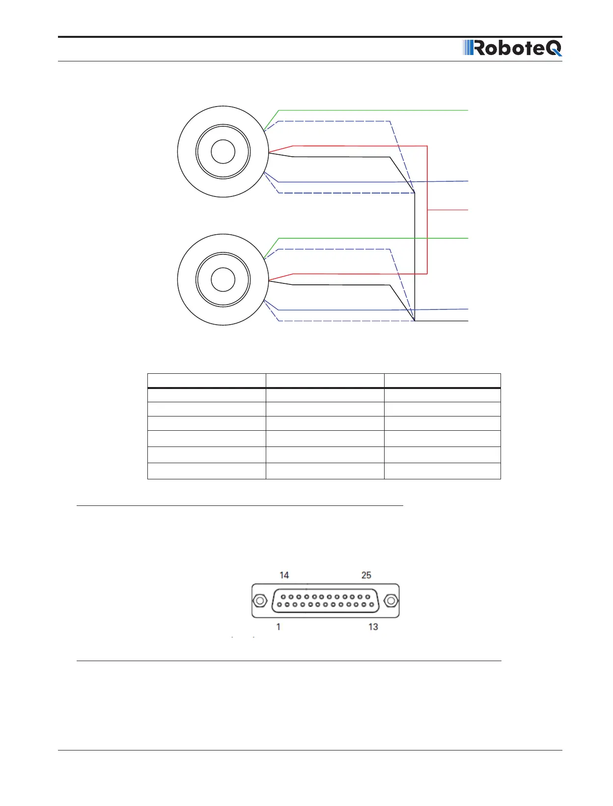
Primary
1
2
ASIN1
Secondary 2
Primary
Secondary 1
ASIN2
EXC
GND
Secondary 2
The table below shows the signals assignment on the 25-pin connector.
TABLE 5.
Signal Pin Number Pin Name
Sin1 9 ASIN1
Cos1 10 ACOS1
Sin2 24 ANA7/ASIN2
Cos2 12 ANA8/ACOS2
Exc 17 ANA4/EXC
GND 1-5 or 13 GND
Commands and I/O Connections
Connection to RC Radio, Microcomputer, Joystick and other low current sensors and
actuators is done via the DB25 connector. The functions of many pins vary depending on
controller model and user configuration. Pin assignment is found in the table below.
FIGURE 9. Main Connector pin locations